Other Parts Discussed in Thread: CONTROLSUITE
Hi all,
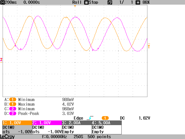
I'm planning to control a motor using TI's DMClib. My motor is equipped with a resolver, but not a common one: It just needs a 5V supply and outputs the sine and cosine signals, which are already demodulated and filtered. It outputs four periods per mechanical turn. Since the motor has four pole pairs, this should be helpful.
When reading the module documentation, which comes with the controlSuite, I was wondering about Figure 1, showing the absolute, demodulated and filtered sine signal. Where is the negative half period of the wave? Was it rectified? If yes, how should you obtain the exact angle of the rotor?
And second question: How do I calculate an appropriat value for the variable "SignalGain"?
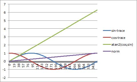
So far, I fed the normalized sine and cosine signals directly into the position_speed_calc()-function, bypassing the demodulator_calc() and filter_calc() functions. But the output values are in the dimension of 10^24(!) when watching them in debug mode. And at the moment I'm a bit stuck at this point.
Thanks for your help!