Hİ,
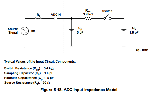
Do I make mistakes ADC settings? Can you help please. I am having problem reading a correct value of input voltage.
This code is built for ezdsp so it includes setup for ADC internal voltage reference, ADC_Cal is also called, ADC clock is setup, Epwm, SOC trigger, ADC control register etc, every thing is setup properly.
Since its setup for internal voltage reference i..e. REF_SEL = 0.
The AdcMirror.ADCRESULT0 is 189
With the above result, do i assume a board problem or there is something i am missing.If i connect an external voltage supply (0-3v), it may damage the board.
Any suggestions would be appreciated
below is the code only for ADC.
#include<stdio.h>
#include<stdlib.h>
#include<math.h>
#include "DSP28x_Project.h"
//------------------------------------------------------
// parametros de arranque ADC
#if (CPU_FRQ_150MHZ) // Default - 150 MHz SYSCLKOUT
#define ADC_MODCLK 0x3 // HSPCLK=SYSCLKOUT/2*ADC_MODCLK2=150/(2*3)=25.0 MHz
#endif
#if (CPU_FRQ_100MHZ)
#define ADC_MODCLK 0x2 // HSPCLK = SYSCLKOUT/2*ADC_MODCLK2 = 100/(2*2) = 25.0 MHz
#endif
#define ADC_CKPS 0x1 // ADC module clock = HSPCLK/2*ADC_CKPS=25.0MHz/(1*2)=12.5MHz
#define ADC_SHCLK 0xf // S/H width in ADC module period = 16 ADC clocks
//-------------------------------------------------------
//Definimos las variables globales
float a;
float sal_process=0;
float sp=0;
//-------------------------------------------------------
//Declaracion de las funciones.
interrupt void cpu_timer1_isr(void);
void leerADC(void);
//-------------------------------------------------------
//Inicio del programa principal
main()
{
// Step 1. Inicializacion del sistema de control:
InitSysCtrl();
// Ajuste de reloj especifico para este ejemplo:
EALLOW;
SysCtrlRegs.HISPCP.all = ADC_MODCLK; // HSPCLK = SYSCLKOUT/ADC_MODCLK
EDIS;
// Step 2.
//Borrar todas las alarmas e inicializar la tabla PIE vector:
DINT;
// Initialize the PIE control registers to their default state.
InitPieCtrl();
// Disable CPU interrupts and clear all CPU interrupt flags:
IER = 0x0000;
IFR = 0x0000;
// Inicialización de la tabla de vectores del móduloPIE
InitPieVectTable();
//Configuración del módulo ADC
InitAdc();
// Specific ADC setup for this example:
AdcRegs.ADCTRL1.bit.ACQ_PS = ADC_SHCLK;
AdcRegs.ADCTRL3.bit.ADCCLKPS = ADC_CKPS;
AdcRegs.ADCMAXCONV.all= 0x1;
AdcRegs.ADCTRL1.bit.SEQ_CASC = 0x1; // 1 Cascaded mode
AdcRegs.ADCTRL1.bit.CONT_RUN = 0x1; // Setup continuous run
AdcRegs.ADCCHSELSEQ1.bit.CONV00 = 0x0; // Setup ADCINA0 as 1st SEQ1
AdcRegs.ADCCHSELSEQ1.bit.CONV01 = 0x1; // Setup ADCINA1 as 2nd SEQ1
// configuro GPIO(64-87) como GPIO outputs.
EALLOW;
GpioCtrlRegs.GPCMUX1.all = 0x00000000;
GpioCtrlRegs.GPCDIR.all = 0xFFFFFFFF;
EDIS;
// ISR functions found within this file.
EALLOW; // Esto es necesario para escribir a registros EALLOW protegidas
PieVectTable.XINT13 = &cpu_timer1_isr;
EDIS; // Esto es necesario para desactivar escribir EALLOW registros protegidas
// Inicializar el dispositivo periférico. Esta se
// Encuentra en DSP2833x_CpuTimers.c
InitCpuTimers();
// Configurar la CPU-Timer 1, para interrumpir cada segundo:
// 150MHz CPU Freq, 2 segundo período (en uSeconds)
ConfigCpuTimer(&CpuTimer1, 150,1000000);
CpuTimer1Regs.TCR.all = 0x4001; // Use write-only instruction to set TSS bit = 0
// Step 5. User specific code, enable interrupts:
// Habilitar CPU INT13 que está conectado a la CPU-Timer 1.
IER |= M_INT13;
// Habilitar interrupciones globales y la mayor prioridad en tiempo real de los eventos de depuración:
EINT; // Habilitar la interrupción INTM Global
ERTM; // Habilitar DBGM Global interrupción en tiempo real
for(;;);
}
interrupt void cpu_timer1_isr(void)
{ unsigned int a_int,aux1;
float output_pid;
leerADC();
output_pid=sal_process;
if(output_pid>100)
output_pid=100;
if(output_pid<0)
output_pid=0;
a= (output_pid * 65535)/100;
a_int= floor(a+0.5);
GpioDataRegs.GPCDAT.bit.GPIO76 = 1;
GpioDataRegs.GPCDAT.bit.GPIO73 = 0; // coloco en bajo MLBYTE para leer '8 LSB'
GpioDataRegs.GPCDAT.bit.GPIO74 = 0; // coloco en bajo WR(negada) para cargar los '8 LSB'
// en el DAC
// Cargo los bits menos significativos GPIO
aux1= a_int;
GpioDataRegs.GPCDAT.bit.GPIO64= aux1 & 0x0001;
aux1= aux1 >> 1;
GpioDataRegs.GPCDAT.bit.GPIO65= aux1 & 0x0001;
aux1= aux1 >> 1;
GpioDataRegs.GPCDAT.bit.GPIO67= aux1 & 0x0001;
aux1= aux1 >> 1;
GpioDataRegs.GPCDAT.bit.GPIO68= aux1 & 0x0001;
aux1= aux1 >> 1;
GpioDataRegs.GPCDAT.bit.GPIO69= aux1 & 0x0001;
aux1= aux1 >> 1;
GpioDataRegs.GPCDAT.bit.GPIO70= aux1 & 0x0001;
aux1= aux1 >> 1;
GpioDataRegs.GPCDAT.bit.GPIO71= aux1 & 0x0001;
aux1= aux1 >> 1;
GpioDataRegs.GPCDAT.bit.GPIO72= aux1 & 0x0001;
DELAY_US(1L);
GpioDataRegs.GPCDAT.bit.GPIO74 = 1; // coloco en alto WR(negada)
// en el DAC
GpioDataRegs.GPCDAT.bit.GPIO73 = 1; // coloco en bajo MLBYTE para leer '8 MSB'
GpioDataRegs.GPCDAT.bit.GPIO74 = 0; // coloco en bajo WR(negada) para cargar los '8 MSB'
// en el DAC
// Cargar los bits mas significativos GPIO
aux1= aux1 >> 1;
GpioDataRegs.GPCDAT.bit.GPIO64= aux1 & 0x0001;
aux1= aux1 >> 1;
GpioDataRegs.GPCDAT.bit.GPIO65= aux1 & 0x0001;
aux1= aux1 >> 1;
GpioDataRegs.GPCDAT.bit.GPIO67= aux1 & 0x0001;
aux1= aux1 >> 1;
GpioDataRegs.GPCDAT.bit.GPIO68= aux1 & 0x0001;
aux1= aux1 >> 1;
GpioDataRegs.GPCDAT.bit.GPIO69= aux1 & 0x0001;
aux1= aux1 >> 1;
GpioDataRegs.GPCDAT.bit.GPIO70= aux1 & 0x0001;
aux1= aux1 >> 1;
GpioDataRegs.GPCDAT.bit.GPIO71= aux1 & 0x0001;
aux1= aux1 >> 1;
GpioDataRegs.GPCDAT.bit.GPIO72= aux1 & 0x0001;
DELAY_US(10L);
GpioDataRegs.GPCDAT.bit.GPIO74 = 1; // coloco en alto WR(negada)
// en el DAC
GpioDataRegs.GPCDAT.bit.GPIO76 = 0; // llevo LD a bajo para covertir
DELAY_US(1L);
GpioDataRegs.GPCDAT.bit.GPIO76 = 1; // retorno a alto para finalizar la conversion
// The CPU acknowledges the interrupt.
EDIS;
}
void leerADC()
{
float inadc1=0, inadc2=0;
AdcRegs.ADCTRL2.bit.RST_SEQ1 = 0x1;
AdcRegs.ADCTRL2.bit.SOC_SEQ1 = 1; // Start ADC conversion
inadc1 = AdcMirror.ADCRESULT0;
inadc2 = AdcMirror.ADCRESULT1;
sal_process=(inadc1*100)/4096;
sp=(inadc2*100)/4096;
AdcRegs.ADCTRL2.bit.RST_SEQ1 = 0x1;
}
//===========================================================================
// No more.
//===========================================================================


