This thread has been locked.

If you have a related question, please click the "Ask a related question" button in the top right corner. The newly created question will be automatically linked to this question.

Table is located at the wrong place after compile and link

Other Parts Discussed in Thread: TMS320F28062, CONTROLSUITE, MOTORWARE, TMS320F28069M, TMS320F28069

Hello,

I have been running Code Composer on a project that began with the BLDC sensored example code for F28069 and has had code added to it.  I recently started using the RFFT example from the DSP libraries to take the FFT of arrays.  When I first pulled this code in I tested it and it worked on the RFFT example of two sinewaves summed together.  At some point I started getting garbage in the FFT result and as I have looked into it, the sinewave table that is used to calculate the test waveform and the twiddle factors is messed up.  The following lines are in the MEMORY and SECTIONS part of the .cmd file, respectively:

   FPUTABLES   : origin = 0x3FD860, length = 0x0006A0 /* FPU Tables in Boot ROM */

   FPUmathTables    : > FPUTABLES,  PAGE = 0, TYPE = NOLOAD

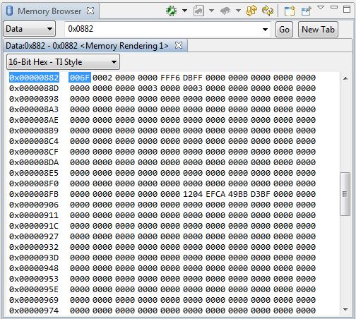
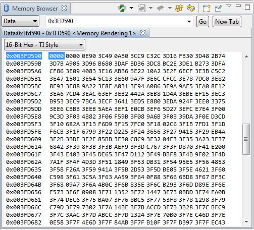
These were taken from the RFFT example code.  When I go to location 0x3FD860 in the memory browser, after loading the code (and before running it), I see values somewhere well into the table.  If I scroll upward, I see the start of the table is at 0x3FD590.   However, the code still thinks the table is at 0x3FD860 and so the values it reads are wrong, and those values read beyond the end of the table (which is at 0x3FDA90) are garbage.   Why is it locating the table in the wrong place?

  • OK - I've learned more.  This table is in Boot ROM and therefore is not loaded.  It should be hardcoded at 0x3FD860.  That being the case, it is (extremely) unlikely that the table has moved.  Is there some kind of MMU or other interpreter that would cause the memory to appear at a different location?   With an offset of 720 decimal it seems unlikely that there are stuck bits causing the offset. 

  • Here is what is seen in the memory browser around 0x3FD860.  FPUsinTable is at 0x3FD860 but it is in the middle of the table:

    0x3FD84C -0.9142098 -0.9191139
    0x3FD850 -0.9238795 -0.9285061
    0x3FD854 -0.9329928 -0.937339
    0x3FD858 -0.9415441 -0.9456073
    0x3FD85C -0.9495282 -0.953306
    0x3FD860 FPUsinTable
    0x3FD860 -0.9569404 -0.9604305
    0x3FD864 -0.9637761 -0.9669765
    0x3FD868 -0.9700313 -0.97294
    0x3FD86C -0.9757021 -0.9783174
    0x3FD870 -0.9807853 -0.9831055

  • Can someone from T.I. help with this? 

  • Mitch, 

    After playing about for a week (see did not see this post, as we did know that this was the problem) we have found the same problem and came to the same result. The only difference is that we had a F28069 which worked as expected, but for the F28062 the start address for the FPUTABLES was at 0x3FD590, the same as what you found.

    Did you get any answers from TI on this, or have you managed to find out the problem?

    Any feedback on this would be hugely appreciated. 

    Many thanks

  • Will,

    No, I have not heard anything further from T.I. on this.  I finally changed the .CMD file to locate the FPUTABLES at the address it appears to be at and now things seem to work okay (on this one unit).  Our plan is to move to a different processor (F28M35) so I haven't spent much more time trying to root cause it.  It does sound like a problem that is going to have to be addressed sooner or later, however.  

    In my situation the tables originally appeared to be in the right place and then after code development they appear to be at the new location.  Did you see a similar change or is the table location simply a function of which processor you are using?

    Regards,

    Mitch

  • Mitch, 

    I'm not sure that TI are going to address it, every time I contact them, they pass the buck to someone else, who then turns you back to TI!

    We have had 50 brds made from two different supplier, using the F28062, therefore the chances are it is not a silicon problem. We have tested a handful of samples now, and the problem is consistent. 

    What I find strange is that we developed the product on the F28069, and we saw no problems with this. We have migrated to the F28062, and now the problem has occurred - madness!

    I wonder if my CCS and F28062s are in still in warranty?!

    Will

  • Mitch,

    Would it be possible for you to post your project files with just the RFFT snippet in it?

  • I must be missing something.  Why don't you just change your .CMD file to say:

    FPUTABLES : origin = 0x3FD590, length = 0x0006A0 /* FPU Tables in Boot ROM */

    It's probably just a typo.

    Regards,

    Bill

  • Bill,

    As was mentioned earlier, I added the RFFT code example to my code early on and it worked correctly.  No need to change the .CMD file for that.  After additional coding and coming back to use of FFT functions, however, partial garbage results unless the .CMD file is changed to point to the new location.  Also, the RFFT example, previously added to my code, produces partial garbage (partial garbage because part of the table is populated with sine or cosine values while the rest is populated with whatever is next to the FPUTABLES).

    Regards,

    Mitch

  • Bill,

    I'm not sure that it is a typo in the CMD file, as we have got the correct data at the TI specified address for the F28069, the micro Mitch is having problems with, but when we migrate the exactly same project:

    main()

    {

    double result = sin(1.0);

    }

    to the F28062, the data at the same predefined start address is not the same as it is for the F28069. We can change the start address of the FPUTABLES, and that is what we have done, however how do we know that the next 50 brds we get in, will have the FPUTABLES in the TI location? Its not really a production safe solution.

    Many thanks

    Will

  • Could you post the bootrom version, checksum, part ID and revision for the devices that have the incorrect table entries. 

    You can find that info at these locations:

    0x3F FFB9
    0x3F FFBA Boot ROM Version Number
    0x3F FFBB MM/YY of release (in decimal)
    0x3F FFBC Least significant word of checksum
    0x3F FFBD . . .
    0x3F FFBE . . .
    0x3F FFBF Most significant word of checksum

    PARTID   0x3D 7E80 1 Part ID Register
    CLASSID 0x0882       1 Class ID Register
    REVID      0x0883      1 Revision ID Register

  • Vishal, 

    Thanks for the reply. Please find below a few screenshots of the memory at the requested locations:

    0x3F FFB9:


    0x3D 7E80:

    0x0882:

    Memory at the address where I think that the FPU ROM starts:

    Memory at the address where TI specify the FPU address to start:

    Many thanks for your help

    Will

  • How about the part numbers that are on-top of the chip's package?

    My guess is that you have

    TMS320F28062F

    devices. These are a different revision of the 6x series chip which replaces some of the regular ROM with our special ROM for InstaSPIN-FOC.  The entire ROM on these special devices is also execute only, no read access.


  • Will, 

    Thanks for the 28062 data. Did you have the same issue as Mitch with the 28069 tables as well?? If you did could you kindly post the content of its ID registers. We are going through the part and rev numbers to identify any changes that may have been made to the ROM.

  • Chris, 

    Thanks for the post. We are using the F28062F, as suggested. However looking through all the documentation, and the associated cmd file, which comes with ControlSUITE, everywhere points to the same start address 0x0860:

    controlSUITE\device_support\f2806x\v136\F2806x_common\cmd

    or

    http://www.ti.com/lit/ug/spruh18d/spruh18d.pdf (page 192 and 193)

    There is also no mention of an address change in the FOC manual:

    http://www.ti.com/lit/ug/spruhi9a/spruhi9a.pdf

    However after much searching I have found the document here:

    http://www.ti.com/lit/ug/spruhj1c/spruhj1c.pdf (page 235).

    Is the change of address a little too hidden?

    Either way - Chris thanks so much for solving the problem, and Vishal thanks for your help too. Much appreciated.

    Will 

  • Hi, Will.

    A couple questions.

    1. Are you using the 62F on purpose?  The point of the 62F devices is to be used with the associated system solution software (InstaSPIN through MotorWare).  Of course, you can use the controlSUITE software on these devices as well, as long as you know that you will need to link in items like IQMath to your project as they are no longer in ROM.  However, the 62F costs more than the 62 device, so it's really only worth use the 62F if you are using InstaSPIN primarily.

    2.  I agree that we aren't communicating this difference well enough.  It previously was in the rather short TRM document, but was moved to the very, very long InstaSPIN UG, so it's effectively hidden.

    My question for you as we try to improve this communication is:
    where did you look first?

    We will obviously add this to the Datasheet, but would be nice to know if you looked other places as well.

    Did you read the www.ti.com/device/tms320f28062f page?  Wondering if we should highlight this front and center on the description.


  • All,

    I'm using an 'F' series part as well.  The only remaining mystery for me is why I thought I had RFFT working early on.  Must have had enough of the table present to produce two sine peaks in the FFT and make it look as if the function was working.  Given the above, however, I have to believe the table has always been in the new location. 

    Thanks for resolving the problem,

    Mitch

  • Mitch,

    I believe some of the IQmath functions still exist in the ROM at the original location.

    We are updating the datasheet and will add this note at the top of eavery product folder for an F and M device.  Hope this solves the issue for the next customers. Sorry about that!

    Special Note

    These devices have special motor control software in execute only ROM to enable InstaSPIN-FOC or InstaSPIN-MOTION solutions, with system software support through MotorWare. While standard C2000 controlSUITE software can be used with these devices please note that this special ROM replaces the standard ROM, meaning certain software functions that controlSUITE projects expect to be in ROM will need to be linked into the project.  Please see the InstaSPIN-FOC and InstaSPIN-MOTION Memory Considerations section of the InstaSPIN User’s Guide or the Memory section of the datasheet for more details.

  • Chris, 

    We are using the F series just for some preproduction brds as they were more readily available. Our production solution is the std F28062. I must say that the speed by which TI have addressed this problem, most noticeable on the website is a hugely credit to their customer support and feedback. 

    I would personally make a note in the Technical Reference Manual TM320x2806x Piccolo, which is common to all the 6x products, and is the third datasheet down on the F webpage. On page 192, it show the memory map for the 6x, which would suggest that all the 6x and 6xF/M share the same memory map. 

    Again, thanks for all your help.

    Will

  • Will,

    I apologize that your original post was in October and it took until January for a TI person to respond, and a few more days until someone solved. That's unacceptable

    Glad you are up and running now.

    -Chris


  • I'd just like to add here that a coworker of mine ran into this exact problem today, and it took a fair amount of time to solve because this is still not properly documented in the TMS320x2806x Piccolo Technical Reference Manual (document SPRUH18E).  The last comment in this thread is from January 2014, the latest version of the TRM is dated March 2014, and it is now March 2015.

    The technical reference manual is linked to from the both the TMS320f28069 and TMS320f28069M product pages.  I bring this up simply to show that any reasonable person would assume that document SPRUH18E applies to all members of the 2806x piccolo family, including the insta-spin variants.

    There is no mention in the TRM that the boot ROM locations for the FPUtables is different between the 28069 and the 28069M.  Rather, there is an image of a single memory map, implying that the ROM location of the FPUtables is the same across all 2806x family parts.

    After quite a bit more searching, it appears that the only official TI documentation of this discrepancy is in the InstaSpin-FOC/InstaSpin-Motion User's Guide (document SPRUHJ1F) in a table on page 327.  This appears to be the correct memory map table, and should replace the incomplete table on page 192 of document SPRUH18E.

    Since this issue affects the proper operation of a relatively fundamental aspect of these parts (the ability to properly compute trigonometric functions), it needs to be properly documented in the 2806x family technical reference manual.

  • Aaron,

    This is now being updated into the device TRMs (instead of just the InstaSPIN TRM supplement). I agree that if for some reason you are using one of these devices w/o the MotorWare InstaSPIN projects (which set-up the memory map for you) there would be no way to understand the issue that is occurring.  We didn't consider this situation when we launched the product (and tried to minimize documentation updates). But especially now that the F2806x Launchpad has 69M silicon it is something we need to make much more apparent.  And we need to do the same for the F2805x and 2x versions.