


I am running HVPM_Sensorless_CLA_F28035 example (HVMotorCtrk+PFCKit_v2.0) from Control Suite in TMS320F28035 environement.
I used TMS320F28335 for some time and graph tool was working fine with the similar buffer code. However, I could not get the graph tool working with TMS320F28035 with CLA.
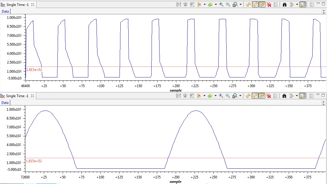
I am trying to graph positive cycle of the simple sinusoidal signal with 60Hz. Whenever the Enableflag is turned to one (whenever the all calculation code is running) graph tool outputting the top figure whenever the EnableFlag is turned to 0 (pretty much nothing goes on) graph tool is outputting bottom figure (possible the last array from the previous cycles).
Graph properties are 200 Buffer size 32 bit Floating point 10000 Sampling Rate Hz
interrupt void Cla1Task1 ( void )
{...
...
if(EnableFlag!=0)
{
...
...
AdcBuf [ ConversionCount ] = ( AdcResult.ADCRESULT8 + AdcResult.ADCRESULT9 ) >> 1;
if (ConversionCount == ADC_BUF_LEN-1)
ConversionCount=0;
else
ConversionCount++;
...
....
}
///AdcBuf definitions are in ClaDataRam0. I also tried Cla1ToCpuMsgRAM ;
#pragma DATA_SECTION(AdcBuf,"ClaDataRam0");
volatile float AdcBuf[ADC_BUF_LEN]; // ADC buffer allocation
#pragma DATA_SECTION(ConversionCount,"ClaDataRam0");
volatile int ConversionCount;
