This thread has been locked.

If you have a related question, please click the "Ask a related question" button in the top right corner. The newly created question will be automatically linked to this question.

Using HVKIT_REV1P1 drive my ACIM,running the proj_lab2b some questios

Other Parts Discussed in Thread: MOTORWARE

Hi,

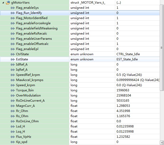
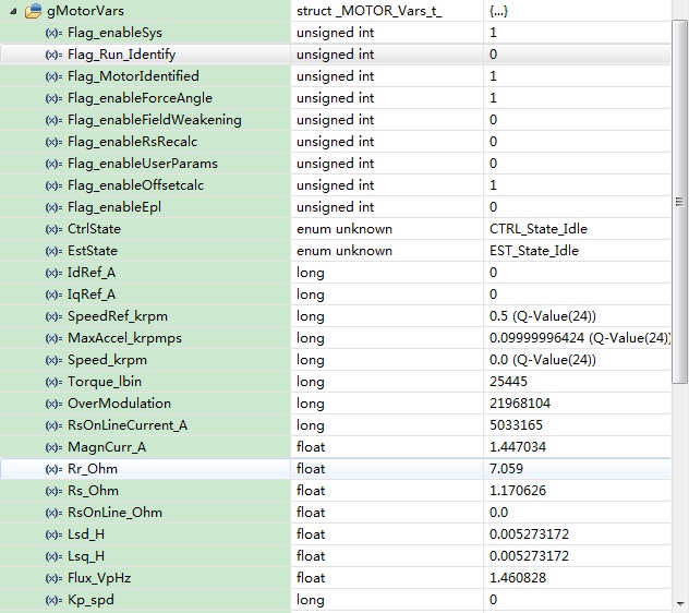
    I'm using HVKIT_REV1P1 drive my ACIM,running the proj_lab2b.The estimation of all parameters have passed and success.Now I set gMotorVars.Flag_Run_Identify & gMotorVars.Flag_enableSys bits,my motor spin with about 2HZ,about 120RPM;Here is my questions:

1,reference the user's guide,I change the  gMotorVars.SpeedRef_krpm,my motor speed not change,the initial value of  gMotorVars.SpeedRef_krpm is 0.1,when i change it to 0.5,the motor speed not change,when i change it to 1.0,the motor speed start change,spin faster a little.

2,reference the user's guide,the gMotorVars.Speed_krpm is the estimate speed,when my motor spin at 2HZ,the gMotorVars.Speed_krpm value about 0.6,why?

3,when i using the spinsta-foc drive the ACIM,Need to pay attention to what?

Thanks!

  • Immortal,

    Your motor parameters are not identified correctly.

    This could be related to your set-up variables or the voltage bus being used.

    But there is also a known issue with the Motor ID for ACI motors that we are looking to patch in an upcoming MotorWare release (unfortunately the most likely release month is Februrary of '14 as we have two more releases scheduled for November that I'm sure it will NOT make it into).

    There is no issue with the control system working with an ACI with the proper parameters, just in identifying them correctly.


    Let's look first to see if we can ID this motor.

    Are you using the GUI or MotorWare?

    If GUI, please post a screenshot of the GUI just after Motor ID so I can see bus voltage, the ID settings, and ID'd parameters.

    If MotorWare, please post your user.h and a screenshot of the gMotorVars structure with the ID'd parameters (and as much of gmotorVars structure as you can fit into your screenshot).

    During ID does the motor spin continuously from the RampUp state until LockRotor?  During LockRotor testing do you feel the rotor producing good torque?


  • 2465.user.h

    Hi Chris:

         First of all, thank you for your reply.I want to clarify some things,I'm using my own HW,reference to the Ti HW design,not the Ti HW,so I'm using Motorware not the GUI.My motor rated voltage is 80V,rated current is 5A,rated frequence is 200HZ,so I use the motorware HVKIT_REV1P1 code to drive my motor.This is my sampling circuit diagram:

                                                                         Figure1 voltage sample circuit

                                                                        Figure2 current sample circuit

    and my user.h.

    Now,I have some other questions:

    1:when i change the waittime in the user.c USER_setParams(USER_Params *pUserParams) funcation,the parameters of the motor have estimmted by the estimation changed a lot,why?

    when i'm using default value,

             pUserParams->ctrlWaitTime[CTRL_State_Error]         = 0;
    	pUserParams->ctrlWaitTime[CTRL_State_Idle]          = 0;
    	pUserParams->ctrlWaitTime[CTRL_State_OffLine]       = (uint_least32_t)( 5.0 * USER_CTRL_FREQ_Hz);
    	pUserParams->ctrlWaitTime[CTRL_State_OnLine]        = 0;
    
    	pUserParams->estWaitTime[EST_State_Error]           = 0;
    	pUserParams->estWaitTime[EST_State_Idle]            = 0;
    	pUserParams->estWaitTime[EST_State_RoverL]          = (uint_least32_t)( 5.0 * USER_EST_FREQ_Hz);
    	pUserParams->estWaitTime[EST_State_Rs]              = 0;
    	pUserParams->estWaitTime[EST_State_RampUp]          = (uint_least32_t)((5.0 + USER_MOTOR_FLUX_EST_FREQ_Hz / USER_MAX_ACCEL_EST_Hzps) * USER_EST_FREQ_Hz);
    	pUserParams->estWaitTime[EST_State_IdRated]         = (uint_least32_t)(10.0 * USER_EST_FREQ_Hz);
    	pUserParams->estWaitTime[EST_State_RatedFlux_OL]    = (uint_least32_t)( 0.2 * USER_EST_FREQ_Hz);
    	pUserParams->estWaitTime[EST_State_RatedFlux]       = 0;
    	pUserParams->estWaitTime[EST_State_RampDown]        = (uint_least32_t)( 2.0 * USER_EST_FREQ_Hz);
    	pUserParams->estWaitTime[EST_State_LockRotor]       = 0;
    	pUserParams->estWaitTime[EST_State_Ls]              = 0;
    	pUserParams->estWaitTime[EST_State_Rr]              = (uint_least32_t)( 5.0 * USER_EST_FREQ_Hz);
    	pUserParams->estWaitTime[EST_State_MotorIdentified] = 0;
    	pUserParams->estWaitTime[EST_State_OnLine]          = 0;
    
    	pUserParams->FluxWaitTime[EST_Flux_State_Error]     = 0;
    	pUserParams->FluxWaitTime[EST_Flux_State_Idle]      = 0;
    	pUserParams->FluxWaitTime[EST_Flux_State_CL1]       = (uint_least32_t)( 3.0 * USER_EST_FREQ_Hz);
    	pUserParams->FluxWaitTime[EST_Flux_State_CL2]       = (uint_least32_t)( 0.2 * USER_EST_FREQ_Hz);
    	pUserParams->FluxWaitTime[EST_Flux_State_Fine]      = (uint_least32_t)( 4.0 * USER_EST_FREQ_Hz);
    	pUserParams->FluxWaitTime[EST_Flux_State_Done]      = 0;
    
    	pUserParams->LsWaitTime[EST_Ls_State_Error]        = 0;
    	pUserParams->LsWaitTime[EST_Ls_State_Idle]         = 0;
    	pUserParams->LsWaitTime[EST_Ls_State_RampUp]       = (uint_least32_t)( 3.0 * USER_EST_FREQ_Hz);
    	pUserParams->LsWaitTime[EST_Ls_State_Init]         = (uint_least32_t)( 3.0 * USER_EST_FREQ_Hz);
    	pUserParams->LsWaitTime[EST_Ls_State_Coarse]       = (uint_least32_t)( 0.2 * USER_EST_FREQ_Hz);
    	pUserParams->LsWaitTime[EST_Ls_State_Fine]         = (uint_least32_t)(30.0 * USER_EST_FREQ_Hz);
    	pUserParams->LsWaitTime[EST_Ls_State_Done]         = 0;
    
    	pUserParams->RsWaitTime[EST_Rs_State_Error]        = 0;
    	pUserParams->RsWaitTime[EST_Rs_State_Idle]         = 0;
    	pUserParams->RsWaitTime[EST_Rs_State_RampUp]       = (uint_least32_t)( 1.0 * USER_EST_FREQ_Hz);
    	pUserParams->RsWaitTime[EST_Rs_State_Coarse]       = (uint_least32_t)( 2.0 * USER_EST_FREQ_Hz);
    	pUserParams->RsWaitTime[EST_Rs_State_Fine]         = (uint_least32_t)( 7.0 * USER_EST_FREQ_Hz);
    	pUserParams->RsWaitTime[EST_Rs_State_Done]         = 0;

     the result is follow:

                                                                        Figure3  Using default waittime values

    when i chage the default waittime using my waittime value,

             pUserParams->ctrlWaitTime[CTRL_State_Error]         = 0;
    	pUserParams->ctrlWaitTime[CTRL_State_Idle]          = 0;
    	pUserParams->ctrlWaitTime[CTRL_State_OffLine]       = (uint_least32_t)( 10.0 * USER_CTRL_FREQ_Hz);
    	pUserParams->ctrlWaitTime[CTRL_State_OnLine]        = 0;
    
    	pUserParams->estWaitTime[EST_State_Error]           = 0;
    	pUserParams->estWaitTime[EST_State_Idle]            = 0;
    	pUserParams->estWaitTime[EST_State_RoverL]          = (uint_least32_t)( 10.0 * USER_EST_FREQ_Hz);
    	pUserParams->estWaitTime[EST_State_Rs]              = 0;
    	pUserParams->estWaitTime[EST_State_RampUp]          = (uint_least32_t)((30.0 + USER_MOTOR_FLUX_EST_FREQ_Hz / USER_MAX_ACCEL_EST_Hzps) * USER_EST_FREQ_Hz);
    	pUserParams->estWaitTime[EST_State_IdRated]         = (uint_least32_t)(15.0 * USER_EST_FREQ_Hz);
    	pUserParams->estWaitTime[EST_State_RatedFlux_OL]    = (uint_least32_t)( 0.4 * USER_EST_FREQ_Hz);
    	pUserParams->estWaitTime[EST_State_RatedFlux]       = 0;
    	pUserParams->estWaitTime[EST_State_RampDown]        = (uint_least32_t)( 4.0 * USER_EST_FREQ_Hz);
    	pUserParams->estWaitTime[EST_State_LockRotor]       = 0;
    	pUserParams->estWaitTime[EST_State_Ls]              = 0;
    	pUserParams->estWaitTime[EST_State_Rr]              = (uint_least32_t)( 10.0 * USER_EST_FREQ_Hz);
    	pUserParams->estWaitTime[EST_State_MotorIdentified] = 0;
    	pUserParams->estWaitTime[EST_State_OnLine]          = 0;
    
    	pUserParams->FluxWaitTime[EST_Flux_State_Error]     = 0;
    	pUserParams->FluxWaitTime[EST_Flux_State_Idle]      = 0;
    	pUserParams->FluxWaitTime[EST_Flux_State_CL1]       = (uint_least32_t)( 5.0 * USER_EST_FREQ_Hz);
    	pUserParams->FluxWaitTime[EST_Flux_State_CL2]       = (uint_least32_t)( 0.4 * USER_EST_FREQ_Hz);
    	pUserParams->FluxWaitTime[EST_Flux_State_Fine]      = (uint_least32_t)( 10.0 * USER_EST_FREQ_Hz);
    	pUserParams->FluxWaitTime[EST_Flux_State_Done]      = 0;
    
    	pUserParams->LsWaitTime[EST_Ls_State_Error]        = 0;
    	pUserParams->LsWaitTime[EST_Ls_State_Idle]         = 0;
    	pUserParams->LsWaitTime[EST_Ls_State_RampUp]       = (uint_least32_t)( 5.0 * USER_EST_FREQ_Hz);
    	pUserParams->LsWaitTime[EST_Ls_State_Init]         = (uint_least32_t)( 5.0 * USER_EST_FREQ_Hz);
    	pUserParams->LsWaitTime[EST_Ls_State_Coarse]       = (uint_least32_t)( 0.4 * USER_EST_FREQ_Hz);
    	pUserParams->LsWaitTime[EST_Ls_State_Fine]         = (uint_least32_t)(40.0 * USER_EST_FREQ_Hz);
    	pUserParams->LsWaitTime[EST_Ls_State_Done]         = 0;
    
    	pUserParams->RsWaitTime[EST_Rs_State_Error]        = 0;
    	pUserParams->RsWaitTime[EST_Rs_State_Idle]         = 0;
    	pUserParams->RsWaitTime[EST_Rs_State_RampUp]       = (uint_least32_t)( 3.0 * USER_EST_FREQ_Hz);
    	pUserParams->RsWaitTime[EST_Rs_State_Coarse]       = (uint_least32_t)( 5.0 * USER_EST_FREQ_Hz);
    	pUserParams->RsWaitTime[EST_Rs_State_Fine]         = (uint_least32_t)( 10.0 * USER_EST_FREQ_Hz);
    	pUserParams->RsWaitTime[EST_Rs_State_Done]         = 0;

    the result is follow:

                                                                        Figure4  change default waittime values

    2:as above when i change the waittime,the driving effect is better than the default value,why?

    Thank you again for your reply.

    Thanks.


  • I'm going to comment as I go through your user.h file

    #define USER_IQ_FULL_SCALE_VOLTAGE_V      (200.0)

    This is probably too low for full operation. If your ID is correct you have 1.5 V/Hz motor and may run it to 200 Hz, that woudl produce 300V of Bemf. I'd update this to (320.0)....at least once Motor is ID'd. It is usually ok (and better) to lower the FULL_SCALE_VOLTAGE during ID to maximize resolution, especialy for Flux.

    #define USER_ADC_FULL_SCALE_VOLTAGE_V       (178.0059)      // 119.7706 hvkit_rev1p1 voltage scaling

    I haven't done the math on your circuit, just want to make sure that you have and 178.0059 is correct.  You run your bus at 80V and have 178V scaling though?  That's not ideal. Any reason you choose 178?

    FULL_SCALE_CURRENT_A

    Why do you have the same values as the HVKit. Did you keep the exact same current shunt and sense values with no changes?  It's fine for your 5A motor, but you could have adjusted this even further.

    #define USER_MAX_DUTY_CYCLE        (1.309401076758503)

    you should change this to (1.0). Sorry, it's not very well documented today. This variable is actually being renamed in the next  MotorWare release.  When you want to use OverModulation you will set this up to the higher value in your source code, following lab10.

    #define USER_ZEROSPEEDLIMIT   (0.002)

    You have 0.002 * 200 Hz = 0.4 Hz = 24 RPM.  That's a bit low for start-up. I'd recommend initially to set this to 5 Hz and then test to see if you can go lower.  (0.025)

    #define USER_VOLTAGE_FILTER_POLE_Hz  (318.0)

    Again, haven't done the math on your circuit, just want to make sure you have

    #define USER_MOTOR_RATED_FLUX           (0.8165*220.0/50.0)  // sqrt(2/3)* Rated V (line-line) / Rated Freq (Hz)

    This isn't correct.  You say this is an 80V 200Hz motor, correct?

    #define USER_MOTOR_RES_EST_CURRENT      (1.0)

    I'd start this at (0.5) and only increase if the motor doesn't start spinning during RampUp

    #define USER_MOTOR_MAX_CURRENT          (3.0)

    Why 3A and not 5A?  Just safety to start?  That's fine, just realize this will limit the Iq demand from the Speed PI output.

    #define USER_MOTOR_FLUX_EST_FREQ_Hz     (5.0)

    Your motor is 200 Hz, you should set this to (20.0)

    Please default back all of the timing. For your motor it isn't really necessary. It is only required to look at adjusting the timing during ID if the motor needs to spin to a very high speed (for flux estimation) or you have the acceleration set very low.  It's just a time-out feature.  Best not to mess with it for your system.

    Certainly these user settings are effecting the flux ID. Let's try again using my comments.  I do believe this motor should be able to be identified as most of the problems with ACI Motor ID have to do with high current versions where the motor goes instable during testign due to the current controller gains (similar to low inductance motors which we patched with lab2c).

     Were you able ID this motor using the HVMTR kit?

    Does the motor spin continuously from RampUp to LockRotor?


  • One additional thing, let's look at your adcBias values.

    in your expressions view enter

    drv.adcBias.V.Value

    Change them to Q24 variables, and they should match your updated offsets if you update user.h

    The important thing is to make sure that after they first update they aren't changing significantly (at least first 3 or 4 bits should always be stable).

    Especially watch and see if they update during ID at the LockRotor and end Idle states.

  • Hi Chris:

    Thanks a lot for your reply.I've seen your reply about my user.h.Here is my interpretation.

    1:#define USER_IQ_FULL_SCALE_VOLTAGE_V      (200.0)  

    You said " If your ID is correct you have 1.5 V/Hz motor and may run it to 200 Hz, that woudl produce 300V of Bemf. I'd update this to (320.0)....at least once Motor is ID'd.",why 1.5V/Hz?

    2:#define USER_ADC_FULL_SCALE_VOLTAGE_V       (178.0059)      // 119.7706 hvkit_rev1p1 voltage scaling   The value 178.0059 according to our HW design,no particular reason.Should I change our HW design to make this value lower?

    3:FULL_SCALE_CURRENT_A   This value is the same as HVKIT,because the current sample circuit is the same as HVKIT,such as resistance and operational amplifier and gain,so I don't have to change these values?

    4:#define USER_MOTOR_RES_EST_CURRENT      (1.0)  

    You said "I'd start this at (0.5) and only increase if the motor doesn't start spinning during RampUp".Yes when I use 0.5,the motor don't spin,when I use 1.0,the motor spin a while then stop before the EST_State_Lockrotor state comming,I don't know What's the matter.

    5:Current and voltage offset,when I running the estimation I enable the gMotorVars.Flag_enableOffsetcalc bit by CTRL_setFlag_enableOffset(ctrlHandle,gMotorVars.Flag_enableOffsetcalc),so I think the offset is correct.

    6:When I running the estimation the motor don,t spin continuously from RampUp to LockRotor,it's spin after the RampUp state(in the EST_State_IdRated state) and stop before RampDown,some times the motor don.t spin at all of the states form RampUp to LockRotor.

    Other Suggestions is very useful to me.

    Thank you!!!

  • why 1.5V/Hz?

    In your screen shot the Flux_VpHz value is ~1.5.  Multiply this by your highest frequency and this is the Bemf voltage the motor will be producing.

    Should I change our HW design to make this value lower?

    You always want to maximize your resolution of signals. If this is an 80V bus I would design the sensing for the maximum you want to measure, so 85-100 should be fine. You are just throwing away bits of resolution currently.

    3:FULL_SCALE_CURRENT_A

    Ok.

    4:#define USER_MOTOR_RES_EST_CURRENT

    Ok, you did the right thing to increase to make sure it starts RampUp.

    5. Please monitor the adcBias values and insure they aren't changing from the initial calibration. I suspect they are.

    6. Your Motor ID is inaccurate. The motor needs to spin continuosly from RampUp until LockRotor, and it needs to produce some expected torque during LockRotor


  • Hi Chris:

        Thank you all the same!

        I have some doubts.There are some load on my motor rotor,just a small load.Can I ignore it when I running identification?

        Thank you!

  • yes, you can ignore small loads during ID.

    I would try my hints, and if still having an issue you have two options

    1. try to get the parameters from the motor supplier

    2. wait for us to update the Motor ID capability for ACI motors (very likely January/February)

  • I really look forward to the update!

    Thank you & Best Regards.

    Immortal

  • My apologies that it isn't working as expected (and we hoped). We did not test enough ACI motors, especially with the Identification feature.

    I would try my suggestions, I still think this motor should be able to be ID'd with the existing ID software.


  • Hi Chris:

        I'm sorry to bother you again.I found a strange problem.

        I still using my board and execute the lab3c ,to be exact excute any proj_labx.When I running the identification,set gMotorVars.Flag_Run_Identify & gMotorVars.Flag_enableSys bits,I found the DRV_Gpio_LED2 blink slower in the mainISR funcation.

    // toggle status LED
    	if(gLEDcnt++ > (uint_least32_t)(USER_PWM_FREQ_kHz * 1000 / LED_BLINK_FREQ_Hz))
    	{
    		DRV_toggleLed(drvHandle,(GPIO_Number_e)DRV_Gpio_LED2);
    		gLEDcnt = 0;
    	}

    The DRV_Gpio_LED2 blink frequence inital is 5HZ,when I running the identification,it's blink at 3HZ,when I disable the identification it's recover blink at 5HZ,I don't know what worng.Is it lost interrupt or the FAST code in the ROM may change the PWM frequence?Do you have the same problem?

       Thank you!

  • That is really strange that it would be different. The code in ROM uses the same user.h settings that your proj_lab3c would, nothing is 'fixed" for motor ID.

    What PWM frequency and decimation are you using in user.h?

    BTW - I don't think we should be using the PWM_FREQ here, we should be using the ISR rate, which is

    USER_PWM_FREQ_kHz   /   USER_NUM_PWM_TICKS_PER_ISR_TICK

    I think this is a remnant from before we added in the hardware ePWM ADC SOC decimation.

    I'll see if I can look at this later this week to verify...

  • Actually, I decided to check this and I'm not seeing any difference in the LED blink rate at all.

    I tried several combinations....