


Other Parts Discussed in Thread: CONTROLSUITE
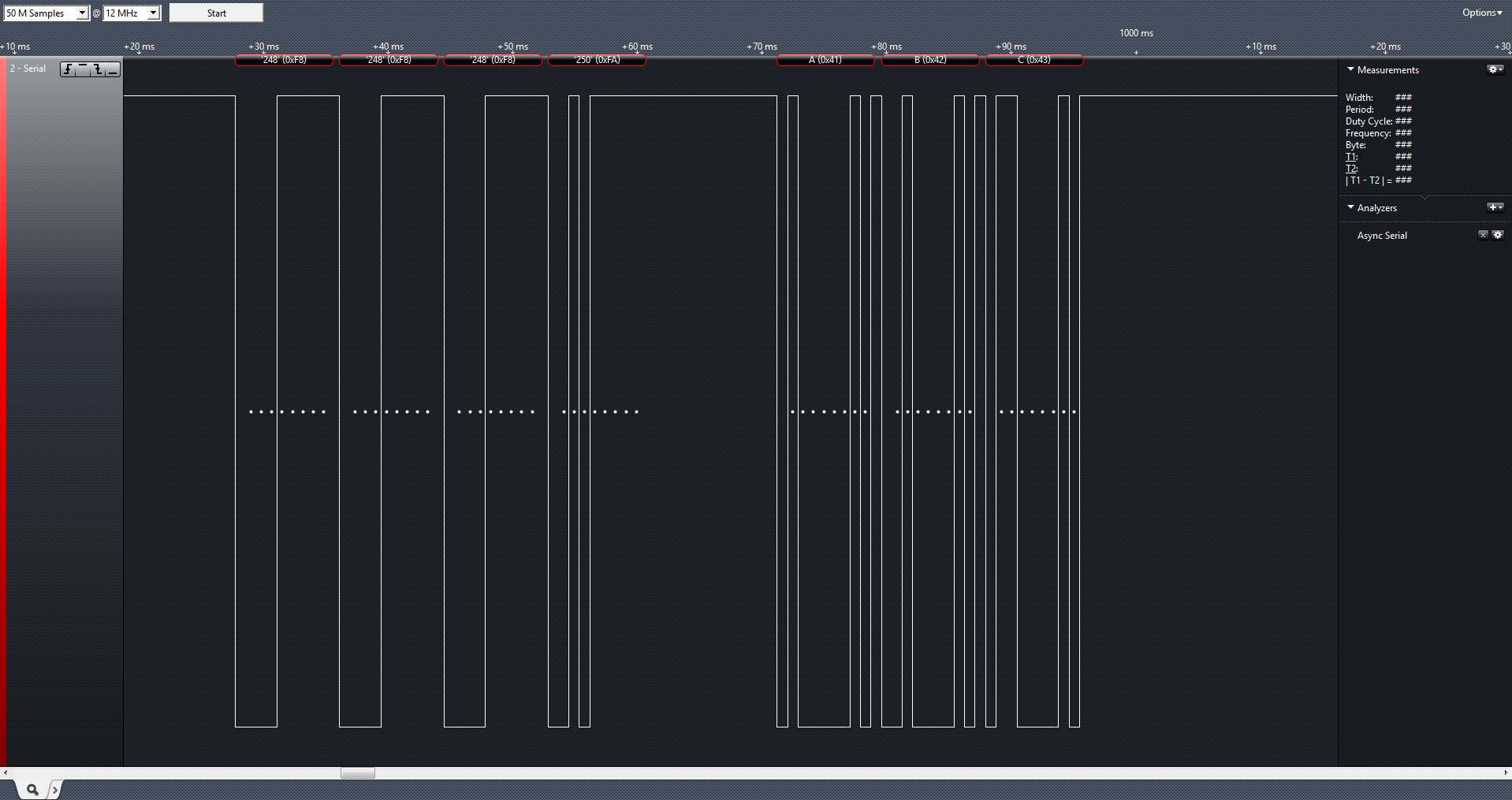
Hi all
Ive been trying to wrap my head around the C2000 Piccolo demoboard pretty powerful stuff very impressed.
Question 1: is how do i measure a signal clock on a GPIO and get the period (in my case im scanning for 10ms high edge to indicate the start of a data packet,
Question 2: How would i get the data bits if the period is 1.66ms high pulse=0.8ms low pulse=0.8ms how do i detect the data bits? I tried using a timer but I just failed to get it working.
I'm getting data packets from the RF receiver and intercepting the rising and falling edges via an on change interrupt vie tried to look at the CPU timer0 and some examples but unfortunately it was of very little help as it deals with measuring intervals using timer interrupts.
please help
This is the code, ive simplified it so its easy to read.
void system_setup(void)
{
    CPU_Handle myCpu;
    PLL_Handle myPll;
    WDOG_Handle myWDog;


    // Initialize all the handles needed for this application
    myAdc = ADC_init((void *)ADC_BASE_ADDR, sizeof(ADC_Obj));
    myClk = CLK_init((void *)CLK_BASE_ADDR, sizeof(CLK_Obj));
    myCpu = CPU_init((void *)NULL, sizeof(CPU_Obj));
    myFlash = FLASH_init((void *)FLASH_BASE_ADDR, sizeof(FLASH_Obj));
    myGpio = GPIO_init((void *)GPIO_BASE_ADDR, sizeof(GPIO_Obj));
    myPie = PIE_init((void *)PIE_BASE_ADDR, sizeof(PIE_Obj));
    myPll = PLL_init((void *)PLL_BASE_ADDR, sizeof(PLL_Obj));
    myTimer = TIMER_init((void *)TIMER0_BASE_ADDR, sizeof(TIMER_Obj));
    myWDog = WDOG_init((void *)WDOG_BASE_ADDR, sizeof(WDOG_Obj));
    mySci = SCI_init((void *)SCIA_BASE_ADDR, sizeof(SCI_Obj));


    // Perform basic system initialization
    WDOG_disable(myWDog);
    CLK_enableAdcClock(myClk);
    (*Device_cal)();

    //Select the internal oscillator 1 as the clock source
    CLK_setOscSrc(myClk, CLK_OscSrc_Internal);

    // Setup the PLL for x10 /2 which will yield 50Mhz = 10Mhz * 10 / 2
    PLL_setup(myPll, PLL_Multiplier_10, PLL_DivideSelect_ClkIn_by_2);

    // Disable the PIE and all interrupts
    PIE_disable(myPie);
    PIE_disableAllInts(myPie);
    CPU_disableGlobalInts(myCpu);
    CPU_clearIntFlags(myCpu);

    // If running from flash copy RAM only functions to RAM
#ifdef _FLASH
    memcpy(&RamfuncsRunStart, &RamfuncsLoadStart, (size_t)&RamfuncsLoadSize);
#endif

    // Setup a debug vector table and enable the PIE
    PIE_setDebugIntVectorTable(myPie);
    PIE_enable(myPie);

    // Register interrupt handlers in the PIE vector table
    PIE_registerPieIntHandler(myPie, PIE_GroupNumber_1, PIE_SubGroupNumber_7, (intVec_t)&cpu_timer0_isr);
    PIE_registerPieIntHandler(myPie, PIE_GroupNumber_1, PIE_SubGroupNumber_4, (intVec_t)&xint1_isr);

    // Enable XINT1 and XINT2 in the PIE: Group 1 interrupt 4 & 5
    // Enable INT1 which is connected to WAKEINT
    PIE_enableInt(myPie, PIE_GroupNumber_1, PIE_InterruptSource_XINT_1);


    // ConfigCpuTimer
    TIMER_stop(myTimer);
    TIMER_setPeriod(myTimer, 50 * 100000); // 100ms overlow
    TIMER_setPreScaler(myTimer, 0);
    TIMER_reload(myTimer);
    TIMER_setEmulationMode(myTimer, TIMER_EmulationMode_StopAfterNextDecrement);
    //TIMER_enableInt(myTimer);
    //TIMER_start(myTimer);


    // Configure GPIO 0-3, 6-19 as outputs.
    GPIO_setMode(myGpio, GPIO_Number_0, GPIO_0_Mode_GeneralPurpose);
    GPIO_setMode(myGpio, GPIO_Number_1, GPIO_0_Mode_GeneralPurpose);
    GPIO_setMode(myGpio, GPIO_Number_2, GPIO_0_Mode_GeneralPurpose);
    GPIO_setMode(myGpio, GPIO_Number_3, GPIO_0_Mode_GeneralPurpose);

    GPIO_setMode(myGpio, GPIO_Number_6, GPIO_0_Mode_GeneralPurpose);
    GPIO_setMode(myGpio, GPIO_Number_7, GPIO_0_Mode_GeneralPurpose);
    GPIO_setMode(myGpio, GPIO_Number_12, GPIO_0_Mode_GeneralPurpose);
    GPIO_setMode(myGpio, GPIO_Number_19, GPIO_0_Mode_GeneralPurpose);

    // Set GPIO output.
    GPIO_setDirection(myGpio, GPIO_Number_0, GPIO_Direction_Output);
    GPIO_setDirection(myGpio, GPIO_Number_1, GPIO_Direction_Output);
    GPIO_setDirection(myGpio, GPIO_Number_2, GPIO_Direction_Output);
    GPIO_setDirection(myGpio, GPIO_Number_3, GPIO_Direction_Output);

    GPIO_setDirection(myGpio, GPIO_Number_6, GPIO_Direction_Output);
    GPIO_setDirection(myGpio, GPIO_Number_7, GPIO_Direction_Output);

    GPIO_setDirection(myGpio, GPIO_Number_12, GPIO_Direction_Input);    // switch input
    GPIO_setPullUp(myGpio, GPIO_Number_12, GPIO_PullUp_Disable);
    GPIO_setDirection(myGpio, GPIO_Number_19, GPIO_Direction_Output);


    // GPIO SCI serial communication.
    GPIO_setPullUp(myGpio, GPIO_Number_28, GPIO_PullUp_Enable);
    GPIO_setPullUp(myGpio, GPIO_Number_29, GPIO_PullUp_Disable);
    GPIO_setQualification(myGpio, GPIO_Number_28, GPIO_Qual_ASync);
    GPIO_setMode(myGpio, GPIO_Number_28, GPIO_28_Mode_SCIRXDA);
    GPIO_setMode(myGpio, GPIO_Number_29, GPIO_29_Mode_SCITXDA);

    // GPIO-12 is XINT1.
    GPIO_setExtInt(myGpio, GPIO_Number_12, CPU_ExtIntNumber_1);

    // Configure XINT1.
    PIE_setExtIntPolarity(myPie, CPU_ExtIntNumber_1, PIE_ExtIntPolarity_RisingAndFallingEdge);

    // Set all 4 leds off.
    GPIO_setHigh(myGpio, GPIO_Number_0);
    GPIO_setHigh(myGpio, GPIO_Number_1);
    GPIO_setHigh(myGpio, GPIO_Number_2);
    GPIO_setHigh(myGpio, GPIO_Number_3);

    // Set PORT 6, 7 and 19.
    GPIO_setLow(myGpio, GPIO_Number_6);
    GPIO_setLow(myGpio, GPIO_Number_7);
    GPIO_setLow(myGpio, GPIO_Number_19);

    // Enable CPU INT1 which is connected to CPU-Timer 0:
    CPU_enableInt(myCpu, CPU_IntNumber_1);

    // Enable TINT0 in the PIE: Group 1 interrupt 7.
    PIE_enableTimer0Int(myPie);

    // Enable external interrupts.
    PIE_enableExtInt(myPie, CPU_ExtIntNumber_1);

    // Enable global Interrupts and higher priority real-time debug events.
    CPU_enableGlobalInts(myCpu);
    CPU_enableDebugInt(myCpu);


interrupt void xint1_isr(void)
{
    // check data
    check_data();

    // Toggle GPIO-6
    GPIO_toggle(myGpio, GPIO_Number_0);
    GPIO_toggle(myGpio, GPIO_Number_6);

    // Acknowledge this interrupt to get more from group 1
    PIE_clearInt(myPie, PIE_GroupNumber_1);
}


void check_data(void)
{
    // Detect pulse falling edge on the GPIO port-12.
    if( GPIO_getData(myGpio, GPIO_Number_12) == 0 ){

    }

    // Detect pulse rising edge on the GPIO port-12.
    if ( GPIO_getData(myGpio, GPIO_Number_12) == 1 ) {


    }
}

