This thread has been locked.
If you have a related question, please click the "Ask a related question" button in the top right corner. The newly created question will be automatically linked to this question.
Hello Everyone,
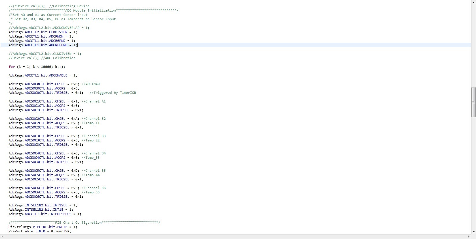
I am programming a TMS320F28069 microcontroller with several ADC channels enabled. There are seven SOCs under utilization, corresponding to ADCINA0, A1, B2, B3, B4, B5, and B6.
Attached with my configuration (Picture #1) and the result I have under debug mode (Picture #2).
As shown in Picture #2, there are three unstable results came from SOC4, SOC5, and SOC6. Apart from those three, the rest are extremely close to 3.3V (no load).
I am still learning, and this is beyond my knowledge and experience at this moment. It would be great if anybody could give some advice.
Thank you!
Fred
Hi,
Can you also attach a screenshot of mapping of ADCRESULT resistors with variables?
Regards,
Gautam
Hi, I also want to know what kind of inputs are these ADCs fed? or are they left floating?
Regards,
Gautam
Hello,
Have you read the errata sprz342g.pdf ?
On page 11 you can read:
------------------------------------
Advisory : ADC: Initial Conversion
Revision(s) Affected : 0, A, B
Details :
When the ADC conversions are initiated by any source of trigger in either sequential or
simultaneous sampling mode, the first sample may not be the correct conversion result.
Workaround(s) :
For sequential mode, discard the first sample at the beginning of every series of
conversions. For instance, if the application calls for a given series of conversions,
SOC0→SOC1→SOC2, to initiate periodically, then set up the series instead as
SOC0→SOC1→SOC2→SOC3 and only use the last three conversions, ADCRESULT1,
ADCRESULT2, ADCRESULT3, thereby discarding ADCRESULT0.
For simultaneous sample mode, discard the first sample of both the A and B channels at
the beginning of every series of conversions.
User application should validate if this workaround is acceptable in their application.
The magnitude of error is significantly reduced by writing a 1 to the ADCNONOVERLAP
bit in the ADCCTRL2 register, which only allows the sampling of ADC channels when the
ADC is finished with any pending conversion. Typically, the difference between the first
sample and subsequent samples, with ADCNONOVERLAP enabled, will be less than or
equal to four LSBs.
----------------------------------
Hope this help you.
Best regards,
Maria
Two of them are fed by Hall Effect current sensors, and five of them are fed by temperature sensors (Analog Devices TMP36GZ). The three channels assigned to temperature sensors were getting unstable data. Thanks!
Thank's for the advice!
By following your suggestion, I changed
AdcRegs.INTSEL1N2.bit.INT1SEL from 1 to 6. Yet the unstable channels were still having the same issue.
I enabled "Continuous Refresh" function in CCS in order to trace voltages changing, and I realized that values come out of those three channels are continuous updating rather than stay at some certain level.
Hello Maria, thanks for your attention and suggestion!
In my original configuration, ADCNONOVERLAP was set to 1, while the values come out of the three unstable channels are constantly changing, rather than stay at a certain level.
Frankly I have not read the errata yet, but your suggestion rings my bell. I am going to take a look at this moment.
Thank you!
Fred,
Can you scope the F28069 ADC pins while they are sampling the temperature sensors? You may need to buffer the the temperature sensor signals if you see disturbances during S/H switching. You can also try to max out the ACQPS values to see if the readings improve.
-Tommy
Tommy,
Whenever any pin is connected to the Oscilloscope, the reading changes to 0 instantly. When disconnecting that pin from the Oscilloscope, the reading goes back to whatever it used to be.
I changed INTSEL to 6, and maxed ACQPS to 3F. It seems like the readings are reasonable on those unstable pins, when being fed by the temperature sensor. Although they returned to unstable after disconnecting temperature sensors.
There is a margin of approximately 1 degree celsius of reading between stable and unstable pins. If I am averaging them, the difference could be ignored. I think this is the best solution so far.
Thank you for your time and your suggestions!
And I would like to thank all of E2E members that get involved with my question!
Frederick, try attaching the screenshots of the Graphs plotted. Averaging is a solution or also you can make use of filters. Here, averaging seems to be the best option. Also, ADC values are never constant, there will be slight variation.
Regards,
Gautam