I need some assistance with trying calculate period using the “ecap” module.
I put an example together that generates an interrupt every 5Hz with a duty cycle of 50% I then feed that square wave running at 5hz back into the board to the ecap module and "attempt" to verify the period. I was able to setup the ecap module im able to hit breakpoints using the ecap ISR
My Question is :
I’m confused just how to calculate the period I have setup CPU to run at 50mhz and I understand the capture counter cycles down until the programmed pulse edge is detected as stated in the datasheet but still no luck get my calculation right…
Ive been reading the datasheet on this subject for days but no luck.
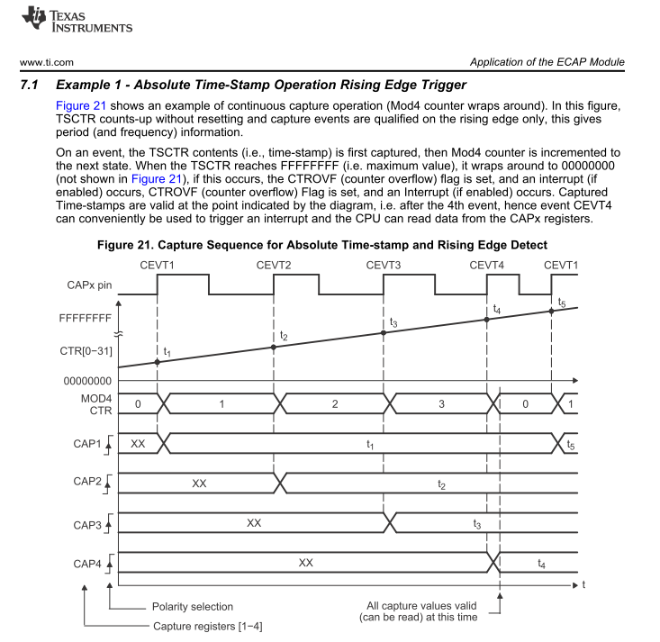
http://www.ti.com/lit/ug/sprufz8a/sprufz8a.pdf
Thanks
#include <stdio.h>
#include <file.h>


#include "DSP28x_Project.h"

#include "f2802x_common/include/adc.h"
#include "f2802x_common/include/clk.h"
#include "f2802x_common/include/flash.h"
#include "f2802x_common/include/gpio.h"
#include "f2802x_common/include/pie.h"
#include "f2802x_common/include/pll.h"
#include "f2802x_common/include/pwm.h"
#include "f2802x_common/include/cap.h"
#include "f2802x_common/include/timer.h"
#include "f2802x_common/include/wdog.h"
#include "f2802x_common/include/sci.h"

// Interrupt function prototypes
interrupt void cpu_timer0_isr(void);
interrupt void xint1_isr(void);
interrupt void sciaTxFifoIsr(void);
interrupt void sciaRxFifoIsr(void);
interrupt void scibTxFifoIsr(void);
interrupt void scibRxFifoIsr(void);
interrupt void ecap1_isr(void);

// System functions prototypes.
void InitECapture(void);
void system_setup(void);
void scia_fifo_init(void);


// System data types
uint16_t interruptCount = 0;
ADC_Handle myAdc;
CLK_Handle myClk;
FLASH_Handle myFlash;
GPIO_Handle myGpio;
PIE_Handle myPie;
TIMER_Handle myTimer;
SCI_Handle mySci;
CAP_Handle myCap;


uint32_t value1 = 0;
uint32_t value2 = 0;
void main(void)
{
	// Set system
	system_setup();

    for(;;) {

    	value2 = TIMER_getCount(myTimer);

    }
}


void system_setup(void)
{
    CPU_Handle myCpu;
    PLL_Handle myPll;
    WDOG_Handle myWDog;

    // Initialize all the handles needed for this application
    myCap = CAP_init((void *)CAPA_BASE_ADDR, sizeof(CAP_Obj));
    myAdc = ADC_init((void *)ADC_BASE_ADDR, sizeof(ADC_Obj));
    myClk = CLK_init((void *)CLK_BASE_ADDR, sizeof(CLK_Obj));
    myCpu = CPU_init((void *)NULL, sizeof(CPU_Obj));
    myFlash = FLASH_init((void *)FLASH_BASE_ADDR, sizeof(FLASH_Obj));
    myGpio = GPIO_init((void *)GPIO_BASE_ADDR, sizeof(GPIO_Obj));
    myPie = PIE_init((void *)PIE_BASE_ADDR, sizeof(PIE_Obj));
    myPll = PLL_init((void *)PLL_BASE_ADDR, sizeof(PLL_Obj));
    myTimer = TIMER_init((void *)TIMER0_BASE_ADDR, sizeof(TIMER_Obj));
    myWDog = WDOG_init((void *)WDOG_BASE_ADDR, sizeof(WDOG_Obj));
    mySci = SCI_init((void *)SCIA_BASE_ADDR, sizeof(SCI_Obj));

    // Perform basic system initialization
    WDOG_disable(myWDog);
    CLK_enableAdcClock(myClk);
    (*Device_cal)();

    //Select the internal oscillator 1 as the clock source
    CLK_setOscSrc(myClk, CLK_OscSrc_Internal);

    // Setup the PLL for x10 /2 which will yield :  50Mhz = ( internal 10Mhz OSCCLK  * 10 / 2)
    // [OSCCLK * 10)/2 (OSCCLK * 10)/1]
    /*
     	 3.8.3 PLL-Based Clock Module
		The devices have an on-chip, PLL-based clock module. This module provides all the necessary clocking
		signals for the device, as well as control for low-power mode entry. The PLL has a 4-bit ratio control
		PLLCR[DIV] to select different CPU clock rates. The watchdog module should be disabled before writing
		to the PLLCR register. It can be re-enabled (if need be) after the PLL module has stabilized, which takes
		1 ms. The input clock and PLLCR[DIV] bits should be chosen in such a way that the output frequency of
		the PLL (VCOCLK) is at least 50 MHz.
     */

    PLL_setup(myPll, PLL_Multiplier_10, PLL_DivideSelect_ClkIn_by_2);

    // Disable the PIE and all interrupts
    PIE_disable(myPie);
    PIE_disableAllInts(myPie);
    CPU_disableGlobalInts(myCpu);
    CPU_clearIntFlags(myCpu);

    // If running from flash copy RAM only functions to RAM
#ifdef _FLASH
    memcpy(&RamfuncsRunStart, &RamfuncsLoadStart, (size_t)&RamfuncsLoadSize);
#endif

    // Setup a debug vector table and enable the PIE
    PIE_setDebugIntVectorTable(myPie);
    PIE_enable(myPie);

    // Register interrupt handlers in the PIE vector table
    PIE_registerPieIntHandler(myPie, PIE_GroupNumber_4, PIE_SubGroupNumber_1, (intVec_t)&ecap1_isr);
    PIE_registerPieIntHandler(myPie, PIE_GroupNumber_1, PIE_SubGroupNumber_4, (intVec_t)&xint1_isr);
    PIE_registerPieIntHandler(myPie, PIE_GroupNumber_1, PIE_SubGroupNumber_7, (intVec_t)&cpu_timer0_isr);


    // ConfigCpuTimer
    TIMER_stop(myTimer);
    TIMER_setPeriod(myTimer, 10000000);	// period = (cpu_clock / freq)
    TIMER_setPreScaler(myTimer, 0);
    TIMER_reload(myTimer);
    TIMER_setEmulationMode(myTimer, TIMER_EmulationMode_StopAfterNextDecrement);
    TIMER_enableInt(myTimer);
    TIMER_start(myTimer);

    // Configure GPIO 0-3, 6-19 as outputs.
    GPIO_setMode(myGpio, GPIO_Number_0, GPIO_0_Mode_GeneralPurpose);
    GPIO_setMode(myGpio, GPIO_Number_1, GPIO_0_Mode_GeneralPurpose);
    GPIO_setMode(myGpio, GPIO_Number_2, GPIO_0_Mode_GeneralPurpose);
    GPIO_setMode(myGpio, GPIO_Number_3, GPIO_0_Mode_GeneralPurpose);

    GPIO_setMode(myGpio, GPIO_Number_6, GPIO_0_Mode_GeneralPurpose);
    GPIO_setMode(myGpio, GPIO_Number_7, GPIO_0_Mode_GeneralPurpose);
    GPIO_setMode(myGpio, GPIO_Number_12, GPIO_0_Mode_GeneralPurpose);
    GPIO_setMode(myGpio, GPIO_Number_19, GPIO_0_Mode_GeneralPurpose);

    /* PWM GPIO-4 */
    GPIO_setPullUp(myGpio, GPIO_Number_4, GPIO_PullUp_Disable);
    GPIO_setMode(myGpio, GPIO_Number_4, GPIO_4_Mode_EPWM3A);

    /* ECAP on GPIO-5*/
    GPIO_setPullUp(myGpio, GPIO_Number_5, GPIO_PullUp_Enable);
    GPIO_setQualification(myGpio, GPIO_Number_5, GPIO_Qual_Sync);
    GPIO_setMode(myGpio, GPIO_Number_5, GPIO_5_Mode_ECAP1);


    // Set GPIO output direction
    GPIO_setDirection(myGpio, GPIO_Number_0, GPIO_Direction_Output);
    GPIO_setDirection(myGpio, GPIO_Number_1, GPIO_Direction_Output);
    GPIO_setDirection(myGpio, GPIO_Number_2, GPIO_Direction_Output);
    GPIO_setDirection(myGpio, GPIO_Number_3, GPIO_Direction_Output);

    GPIO_setDirection(myGpio, GPIO_Number_6, GPIO_Direction_Output);
    GPIO_setDirection(myGpio, GPIO_Number_7, GPIO_Direction_Output);

    GPIO_setDirection(myGpio, GPIO_Number_12, GPIO_Direction_Input);	// switch input
    GPIO_setPullUp(myGpio, GPIO_Number_12, GPIO_PullUp_Disable);
    GPIO_setDirection(myGpio, GPIO_Number_19, GPIO_Direction_Output);


    // GPIO SCI serial communication.
    GPIO_setPullUp(myGpio, GPIO_Number_28, GPIO_PullUp_Enable);
    GPIO_setPullUp(myGpio, GPIO_Number_29, GPIO_PullUp_Disable);
    GPIO_setQualification(myGpio, GPIO_Number_28, GPIO_Qual_ASync);
    GPIO_setMode(myGpio, GPIO_Number_28, GPIO_28_Mode_SCIRXDA);
    GPIO_setMode(myGpio, GPIO_Number_29, GPIO_29_Mode_SCITXDA);

    // GPIO-12 is XINT1.
    GPIO_setExtInt(myGpio, GPIO_Number_12, CPU_ExtIntNumber_1);

    // Configure XINT1.
    PIE_setExtIntPolarity(myPie, CPU_ExtIntNumber_1, PIE_ExtIntPolarity_RisingAndFallingEdge);

    // Set all 4 leds off.
    GPIO_setHigh(myGpio, GPIO_Number_0);
    GPIO_setHigh(myGpio, GPIO_Number_1);
    GPIO_setHigh(myGpio, GPIO_Number_2);
    GPIO_setHigh(myGpio, GPIO_Number_3);

    // Set PORT 6, 7 and 19.
    GPIO_setLow(myGpio, GPIO_Number_6);
    GPIO_setLow(myGpio, GPIO_Number_7);
    GPIO_setLow(myGpio, GPIO_Number_19);


    // Setup peripherals used in this example
    InitECapture();


    // Enable CPU INT1 which is connected to CPU-Timer 0:
    CPU_enableInt(myCpu, CPU_IntNumber_1);

    // Enable CPU INT4 which is connected to ECAP1-4 INT:
    CPU_enableInt(myCpu, CPU_IntNumber_4);

    // Enable TINT0 in the PIE: Group 1 interrupt 7.
    PIE_enableTimer0Int(myPie);

    // Enable XINT1 and XINT2 in the PIE: Group 1 interrupt 4 & 5
    PIE_enableInt(myPie, PIE_GroupNumber_1, PIE_InterruptSource_XINT_1);

    // Enable external interrupts.
    PIE_enableExtInt(myPie, CPU_ExtIntNumber_1);


    // Enable eCAP INTn in the PIE: Group 3 interrupt 1-6
    PIE_enableCaptureInt(myPie);


    // Enable global Interrupts and higher priority real-time debug events.
    CPU_enableGlobalInts(myCpu);
    CPU_enableDebugInt(myCpu);
}


void InitECapture()
{

    CLK_enableEcap1Clock(myClk);
    CAP_disableInt(myCap, CAP_Int_Type_All);    // Disable all capture interrupts
    CAP_clearInt(myCap, CAP_Int_Type_All);      // Clear all CAP interrupt flags
    CAP_disableCaptureLoad(myCap);              // Disable CAP1-CAP4 register loads
    CAP_disableTimestampCounter(myCap);         // Make sure the counter is stopped

    // Configure peripheral registers
    CAP_setCapOneShot(myCap);                   // One-shot
    CAP_setStopWrap(myCap, CAP_Stop_Wrap_CEVT2);// Stop at 4 events
    CAP_setCapEvtPolarity(myCap, CAP_Event_1, CAP_Polarity_Rising);    // Falling edge
    CAP_setCapEvtPolarity(myCap, CAP_Event_2, CAP_Polarity_Rising);     // Rising edge
    //CAP_setCapEvtPolarity(myCap, CAP_Event_3, CAP_Polarity_Falling);    // Falling edge
    //CAP_setCapEvtPolarity(myCap, CAP_Event_4, CAP_Polarity_Rising);     // Rising edge

    CAP_setCapEvtReset(myCap, CAP_Event_1, CAP_Reset_Enable);   // Difference operation
    CAP_setCapEvtReset(myCap, CAP_Event_2, CAP_Reset_Enable);   // Difference operation
    //CAP_setCapEvtReset(myCap, CAP_Event_3, CAP_Reset_Enable);   // Difference operation
    //CAP_setCapEvtReset(myCap, CAP_Event_4, CAP_Reset_Enable);   // Difference operation

    CAP_enableSyncIn(myCap);                    // Enable sync in
    CAP_setSyncOut(myCap, CAP_SyncOut_SyncIn);  // Pass through

    CAP_enableCaptureLoad(myCap);

    CAP_enableTimestampCounter(myCap);          // Start Counter
    CAP_rearm(myCap);                           // arm one-shot
    CAP_enableCaptureLoad(myCap);               // Enable CAP1-CAP4 register loads
    CAP_enableInt(myCap, CAP_Int_Type_CEVT4);   // 4 events = interrupt

}


interrupt void cpu_timer0_isr(void)
{

	// counter
    interruptCount++;


    value1 = TIMER_getCount(myTimer);

    // toggle led and gpio port-3 on timer0 overflow
    GPIO_toggle(myGpio, GPIO_Number_3);
    GPIO_toggle(myGpio, GPIO_Number_19);


    // Acknowledge this interrupt to receive more interrupts from group 1
    PIE_clearInt(myPie, PIE_GroupNumber_1);
}


void check_data(void)
{
	// Detect pulse falling edge on the GPIO port-12.
	if( GPIO_getData(myGpio, GPIO_Number_12) == 0 ){

	}

	// Detect pulse rising edge on the GPIO port-12.
	if ( GPIO_getData(myGpio, GPIO_Number_12) == 1 ) {

	}
}

interrupt void xint1_isr(void)
{
	// check data
	check_data();

	// Toggle GPIO-6
    GPIO_toggle(myGpio, GPIO_Number_0);
    GPIO_toggle(myGpio, GPIO_Number_6);

    // Acknowledge this interrupt to get more from group 1
    PIE_clearInt(myPie, PIE_GroupNumber_1);
}

uint32_t t1;
uint32_t t2;
uint32_t period;
interrupt void ecap1_isr(void)
{

	t1 = CAP_getCap1(myCap);
	t2 = CAP_getCap2(myCap);

	period = t2- t1;


    CAP_clearInt(myCap, CAP_Int_Type_CEVT2);
    CAP_clearInt(myCap, CAP_Int_Type_Global);
    CAP_rearm(myCap);

    // Acknowledge this interrupt to receive more interrupts from group 4
    PIE_clearInt(myPie, PIE_GroupNumber_4);
}
.