This thread has been locked.

If you have a related question, please click the "Ask a related question" button in the top right corner. The newly created question will be automatically linked to this question.

FOC with DMClib on F28335

Other Parts Discussed in Thread: TMDSDOCK28335

Hi all,

I'm still trying to complete my field oriented control loops with my Delfino F28335. I'm using the TMDSDOCK28335 and an custom built hardware. The motor is a seperately excited synchron drive with 60kW max and four pole pairs, designed to run on a DC bus up to 400V. Since the planned converter is not ready yet, I'm using a DC power supply @100V with up to 120A. Excitation is fixed to 25V, 3.5A.

My DSP program is a mixture of the example project "sensorless FOC with 28335" and some self-written codes, for example a macro for my sine/cosine rotor position encoder.

I tried to stick with the literature provided with the example project. However, I was not able to get any graphs from CCSv4. (see http://e2e.ti.com/support/microcontrollers/c2000/f/171/p/299935/1047724.aspx if you can help me in this case, thanks :) )

I recently closed the current control loop, where the angle signal is provided from the ramp generator and could speed up the motor to 6000rpm. PI controllers still have their default values.
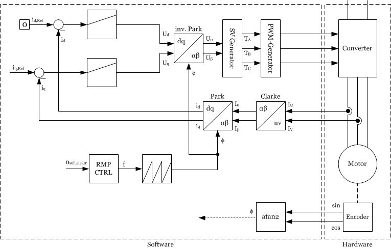
In the next step, I wanted to replace the ramp generator with my calculated angle from the encoder (see attached h-file). Since I cannot use the graph tool, I created two arrays as my own datalog module to read the content in the watch-window.

As you can see, both signals are perfectly aligned. The motor was 600rpm when this data was logged.

So I connected my angle signal to the park and ipark module and removed the angle generator. Then I started with Id,ref=0 and Iq,ref=0.1 and expected the motor to go faster and faster until I set Iq,ref back to 0. But instead I only reached approx. 2000rpm where the motor stopped accelerating. Increasing Id,ref led to even lower speed.
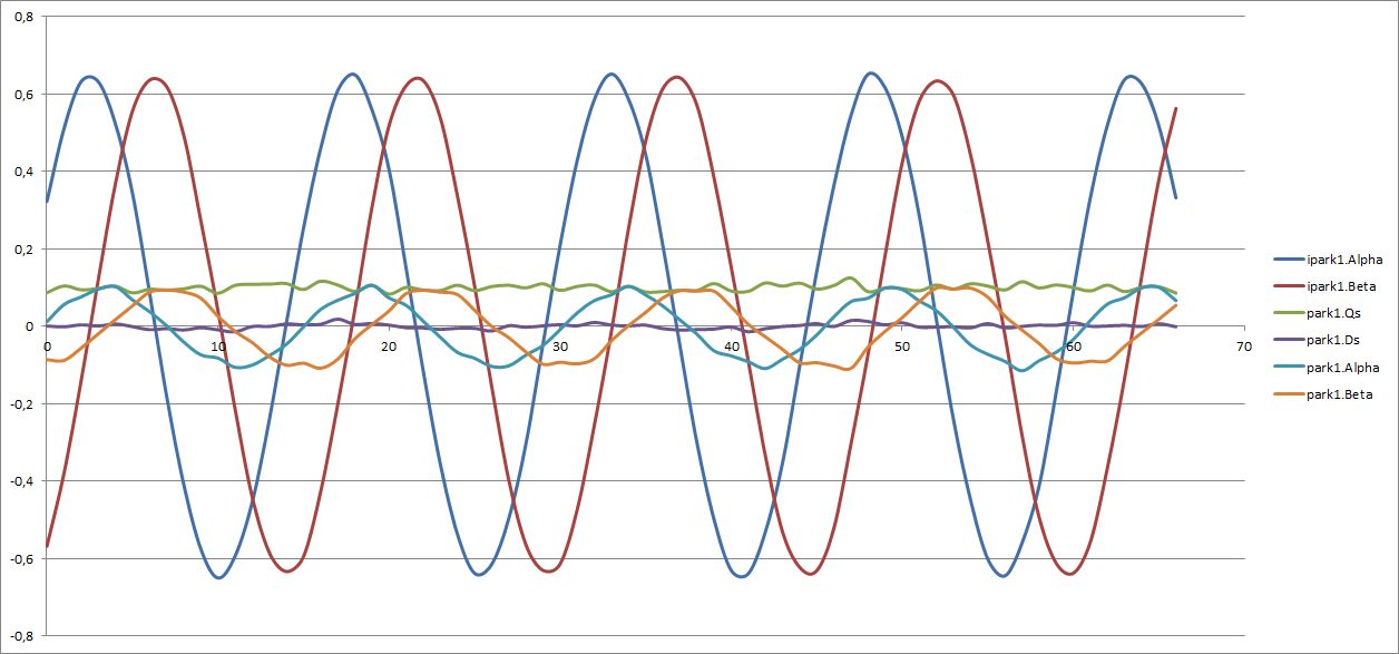
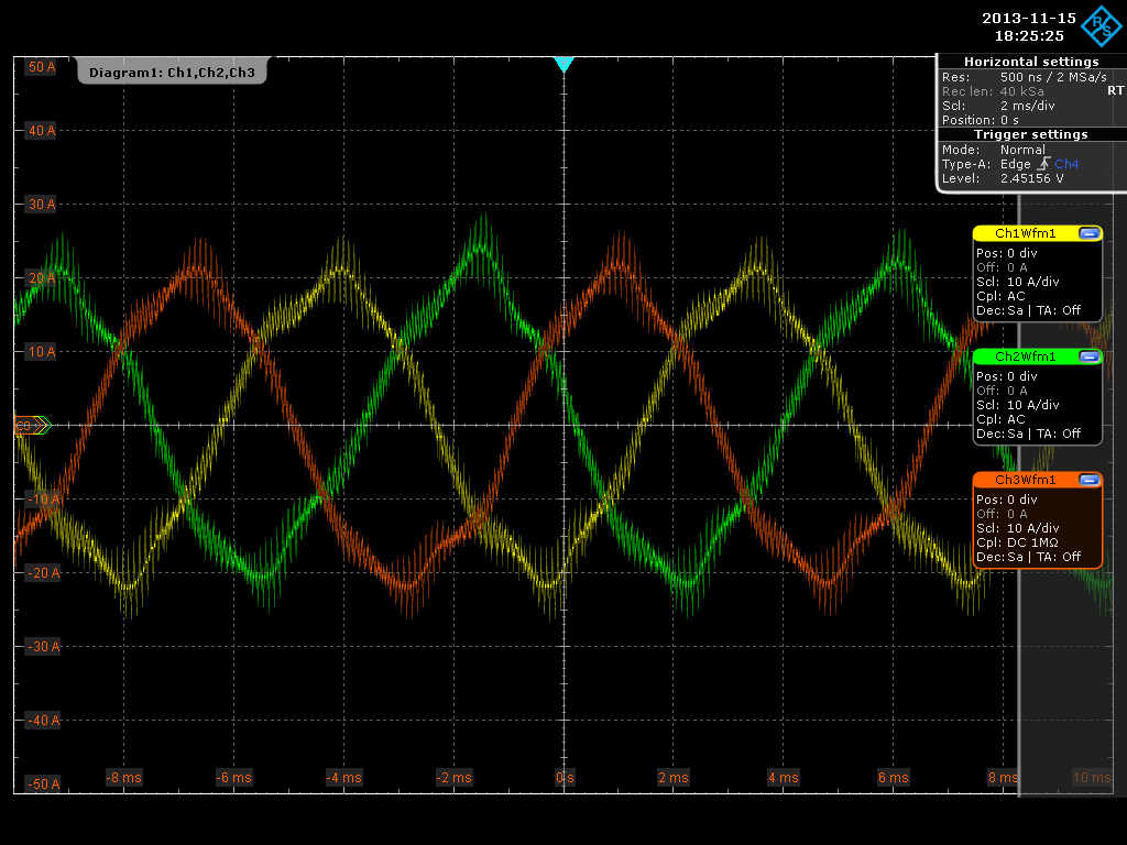
I logged some variables in this moment. Current values are normalized to +-200A. As far as I would say, the signal traces look good. The only thing making me wondering is the large amplitude of ipark.Alpha and ipark.Beta. Here is another screenshot showing all three scaled phase currents and a screenshot of the vallues in the watch window, when the data was logged:
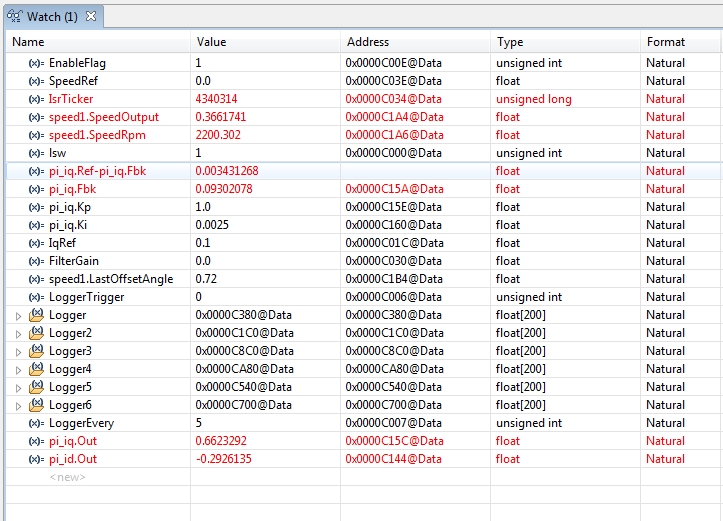
So basically my problem is, that the motor won't speed up to more than 2200rpm. And I have absolutely no idea, why it doesn't. And I hope one of you guys can help me and can give me a hint what I can try.

Thanks and have a great weekend!

rgds, Philipp

SinCosEnc.h
  • " Then I started with Id,ref=0 and Iq,ref=0.1 and expected the motor to go faster and faster until I set Iq,ref back to 0. But instead I only reached approx. 2000rpm where the motor stopped accelerating. Increasing Id,ref led to even lower speed."

    Setting a non zero Iq,ref doesn't guarantee that your rotor will spin to it's maximum.

    And increasing Iq,ref will insure that it does not.


  • Hi,

    first, there was a litte typo: I meant "Increasing Iq,ref".

    I think the problem has something to do with the correct excitation. Normally if you have no mechanical load your stator currents would be very low. However in my case I'm measuring a peak of 20A, resulting in a current feedback of normalized 0.1 (of 200A). So reference and feedback value of the Iq controller are equal, which limits the output of the controller to a certain level.  When I decrease the excitation, the rotor is spnning a little faster beacause stator currents decrease. So I think the motor pushes some reactive power through its windings. By the way, the DC shows a current of ~3A.

    How does increasing Iq,ref insure that it won't speed up?

  • Hi,

    I'm also trying to complete my FOC system with the configuration shown in the attached picture.

    Could you please post the code to export data from the datalog to a file? I'm also having trouble with the Graph Tool (in my case I'm using CCS v5)

    Thanks in advance,

    Matías

  • You just have to create an Array for each channel you want to display. Arrays are defined by

    _iq YourArrayNameHere[x];

    where x is the number of values that can be logged per channel. I chose 200, which is equal to 20ms at 10kHz sampling freq. 

    Then you need some other variables, for example a trigger, to start the logging or another counter if you just want to log every eg. 10th period. I also added a feature setting a variable to a different value after a few samples to record step responses of the controllers.

    You can access the content of the array via the watch window and there pause the permanent refresh and copy the expressions you need to a text file.  

  • Dear Philipp,

    Thanks for the response!! I could succesfully log variables and export them to Matlab.

    Could you solve the problem of speeding up the motor more than 2200 rpm? I'm using a motor with 3000 rpm base speed (50Hz, 2 poles) and I was experimenting the same problem when I tried to speed the motor to more than 1500 rpm. I could solve the problem increasing IdRef to 0.2 (base current = 2A) and with that value I could reach to the max speed.

    In my case I'm connecting the pi_spd block directly to the ipark1 Qs input and a IdRef reference to ipark1 Ds input.

    I'm having a problem with the CUR_MOD macro (http://e2e.ti.com/support/microcontrollers/c2000/f/171/t/311831.aspx) to complete LEVEL5.

    I would aprecciate more information about the estimation of the Theta angle based on current and speed measurements.

    Thanks in advance and Happy New Year,

    Matías.


  • Hi Mathías,

    "solve" might be the wrong term. I did a little workaround which helped me in my case. As I had shown at the very beginning of this topic, I aligned the measured signal with the ramp generator output. This led to the limited speed. 

    So what I did then was to simply apply a constant zero as angle signal to the transformation objects. Then powered the motor and it aligned to its electrical zero degrees position. I read the current angle value from my sensor and set this as a constant offset to be substracted from the measured value. With this method I was able to run up to 7500 rpm what fully met my requirements. 

    Regards,

    Philipp