This thread has been locked.

If you have a related question, please click the "Ask a related question" button in the top right corner. The newly created question will be automatically linked to this question.

InstaSPIN-MOTION unstable beyond a certain speed

Other Parts Discussed in Thread: MOTORWARE, DRV8301, DRV8312

Hi,

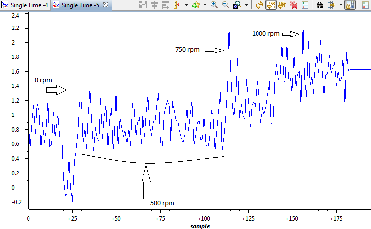
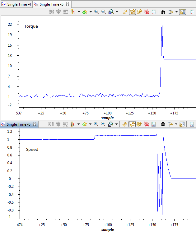
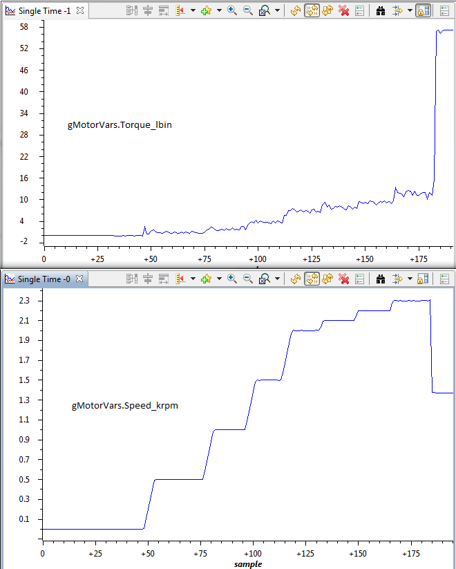
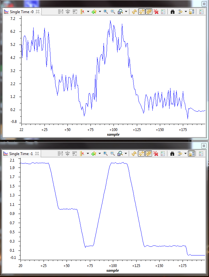
I am running the InstaSPIN-MOTION  project "proj_lab12" that came with Motorware on a custom hardware. I am running a 5krpm 22 pole motor with 2000 count incremental encoder. The system seems to perform pretty well in the speed range of 0 to 1.1krpm. But, every time I increase the speed reference beyond that, the system goes unstable and begins to rotate in the reverse direction and starts oscillating. 

Here is a graph of "SpeedQEP_krpm" when the event occurs:

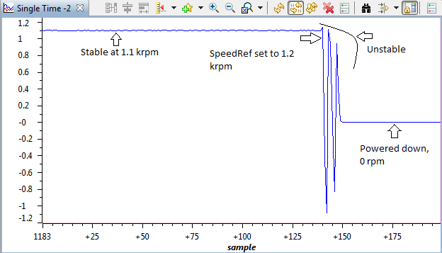
I have the "USER_IQ_FULL_SCALE_FREQ_Hz" at 1100, so I am sure that is not the issue. The encoder is rated for reliable output till 10krpm, so that doesn't seem to be the issue either.

Does this have anything to do with the SpinTAC bandwidth? 

I would appreciate any ideas that might explain this behavior and help in fixing it.

Thanks,
Tamil 

  • I doubt this is a speed controller or scaling issue. First instinct would be to plot the angle being generated as an output from the encoder and input into the ipark module, looking for a discontinuity.  

    Are you using Rs Recal to align the electrical angle?

    At the lower stable speed is the torque response as expected?

  • I tried to plot the encoder output (elecAngle), but it seemed too distorted, probably due to the the low-speed JTAG communication. I earlier ran the setup with a different encoder (an absolute encoder connected through SCI), and I ran into the exact same issue. That makes me think that encoder angle might not be the source.

    Yes, I think I am using Rs Recal to align the electrical angle, which seems to be the default method  in the project.

    At lower speeds of around 500-1000 rpm , the motor runs smoothly, but the plot of "gMotorVars.Torque_lbin" doesn't really make sense to me. Also, controller has difficulty staying at 0 rpm, where it begins to oscillate. The rotation isn't smooth till the SpeedRef is above 300-400 rpm. I have a propeller attached to the rotor, and the zero speed performance does improve when the props are not attached.

    gMotorVars.Torque_lbin:

    -Tamil

  • UPDATE:

    After observing more closely, I found out that when the said instability occurs at 1200 rpm command, the speed of the motor actually raises up rapidly in reality, but it is the "SpeedQEP_krpm" plot that shows the speed as reversing and oscillating. The "gMotorVars.Torque_lbin" plot reflects the rapid increase in speed and torque.


    I wonder if the issue is due to some variable overflowing.

    -Tamil

  • Tamil,

    What is the Inertia and Bandwidth of the system that you are working on?

    What is the sample time that you are using?

    If you wanted to log the angle faster, you could setup a software buffer (see lab 5f for an example).  

    I don't think it is a variable overflowing, since the variables used in SpinTAC are Q24 and in your system 1 pu/s is equal to 6krpm.  Which means that 1.2krpm is only 0.2pu/s.  

  • Hi Adam, 

    Thanks for your reply. I will check the software buffer feature.

    The inertia seems to be around 15-20 Aperkrpm. The bandwidth was 20.

    I later found that the estimated speed was actually close to the real speed even after the instability in the QEP speed. So, I ran the sensorless algorithm in proj_lab5e and I could go well past 1.1krpm. Then, I hit another limit at 2.2krpm, which seems to be due to the maximum limit on the duty cycle, which I had set (to 80%). Just to confirm that, I reduced the max. duty cycle limit to 40% and then the maximum speed I could attain was around 1.2krpm.

    The motor is capable of speeds over 5krpm and in fact I just verified that with another off-the-shelf motor controller. The Kv of the motor is around 110 rpm/volt and my DC bus is at 48V. I wonder why I can get only up to 2.2krpm at 80% duty ratio. Could I be hitting any other limits apart from the max. duty cycle?

    -Tamil

  • Tamil,

    I think your bandwidth seems a little high.  What that large of an inertia, you shouldn't need that large of a bandwidth.  Have you tested it with a lower bandwidth?

    Is this motor an IPM type motor or an SPM type motor?

    Using the QEP speed feedback can it run continuously at speeds less than 1.2krpm?

    Which version of MotorWare are you using?  There have been some recent changes to the Space Vector Modulator that correct some small bugs.  How did you limit the max duty cycle to 80%?  Did you use the #define in user.h?

  • I tried running with a lower bandwidth, of around 5 and it did improve the response at speeds lesser than 500 rpm. But, the issue at high speeds still exist.

    The motor is a SPM type motor. I don't think there is any saliency. I am not sure if you remember, but I had emailed you a video of the motor couple of months ago.

    Yes, it could run continuously at speeds less than 1.2krpm with QEP feedback.

    I was using an older version of Motorware, and set the max duty cycle using #define USER_MAX_DUTY_CYCLE in user.h. I updated to version 1_01_00_11 today and found that option missing in user.h. I wonder where it can be set in this version.

    I ran proj_lab05e again with the latest Motorware and the results seem to be similar. I could increase the speed till 2.3krpm (little over 420 elec  Hz), but once I set the speed reference to 2.4krpm, the "gMotorVars.Torque_lbin" value shot up, along with current consumed and the temperature of my FETs, after which I had to power down the controller to prevent further damage. This is repeatable and every time the rapid rise happens at the same speed command. 

    -Tamil

  • Tamil,

    If it is an SPM type motor than the saliency difference will be marginal.  i do remember the videos that you sent.

    In the latest MotorWare, we have modified the macro definition that sets the maximum modulation.  The is value is located in the user.h:

    USER_MAX_VS_MAG_PU

    • Set USER_MAX_VS_MAG = 1.0 for a pure sinewave with a peak at SQRT(3)/2 = 86.6% duty cycle. No current reconstruction is needed for this scenario.
    • Set USER_MAX_VS_MAG = 2/SQRT(3) = 1.1547 for a pure sinewave with a peak at 100% duty cycle. Current reconstruction will be needed for this scenario (Lab10a-x).
    • Set USER_MAX_VS_MAG = 4/3 = 1.3333 to create a trapezoidal voltage waveform. Current reconstruction will be needed for this scenario (Lab10a-x).
  • Thanks Adam, I have "USER_MAX_VS_MAG" set to 1.0 

    I was curious to know if the issue indeed was occurring at around 2300 RPM, so I added an external tachometer to my setup and found out that the real speed was very different from the estimated speed. I have attached the graphs of the Torque (lb-in), Estimated speed (krpm) and speed measured from external tachometer (rpm). The issue now seems to be happening at a real speed of 4400 RPM, which is around 800 elec. Hz, although the FAST estimator still believes the speed to be 2300 RPM at that point.

    I wonder why there is this huge inconsistency in the estimated speed. The difference between estimated and measured speed was around 100 RPM when the speed was 500 RPM, and it slowly increased, almost linearly, to a difference of 2000 RPM when the speed reference was 2200 RPM. Probably whatever is causing this error is also the cause behind the runaway issue that I am seeing.

    Any thoughts?

    -Tamil

  • In another test, I reduced the bus voltage to 24V, then the controller seems to limit itself at around 2000 RPM estimated (2900 RPM on tachometer). It did not run away like the previous case, but just wouldn't go faster even if the SpeedRef is set higher. I tried changing (increasing/decreasing) the maximum motor current in user.h and it did not seem to have any effect in this range.

    What quantities are used by FAST to estimate the speed? I have the USER_VOLTAGE_FILTER_POLE_Hz at 714.15 (and correspondingly in the hardware). Could this be a factor? I checked my current sensors and they seem to provide a clean output. 

    I tried changing the PWM frequency, ISR ticks and Speed loop ticks, but nothing seems to be solving the issue. 

    -Tamil

  • Tamil,

    If the speed estimate is that off I would say that the estimator is getting bad data; either the motor parameters are incorrect or are changing during operation, or the current/voltage inputs are being corrupted.


  • Wait, you aren't even using FAST for sensorless feedback are you? 

    You have the speed estimate from the encoder counts, right?

    If FAST is still running can you compare the estimate from FAST and your Encoder speed generation?

    Can you try removing the speed feeback entirely and just run in Torque mode with the angle to IPARK coming from your encoder? This will remove any dependency on the speed feedback or controller.


  • No, I stopped using the encoder because with encoder feedback I was not able to go beyond 1200 RPM. I am now running proj_lab5e, which uses FAST feedback. 

    But when I was running proj_lab12 earlier, the FAST estimated speed and encoder measured speed was off by 100-200 RPM.

    Regarding motor parameters, I have enabled Rs recal and the values it calculates seems to be close to datasheet values. For Ls, the estimated values were way off, so I am using the datasheet values from user.h.

    I checked my current feedback and it seems to be clean. I haven't scoped my voltage feedback yet. I will do that and get back.

    I am wondering how it is even able to run the motor smoothly (till 2.3krpm) if the data it receives is way off?

    -Tamil

  • "For Ls, the estimated values were way off, so I am using the datasheet values from user.h."

    That has me concerned.

    What is the datasheet value you're using in user.h?  What did the Motor ID identify?  Post your user.h please.


  • This is a custom motor that we build, so by datasheet values I meant values measured in a LCR meter. The motor windings are Y connected and the line to line inductance I measure was 14uH, which is the value I am using in user.h. The motor ID was not very consistent, but was always higher by an order or two of magnitude.

    Here is my user.h:

    #ifndef _USER_H_
    #define _USER_H_
    /* --COPYRIGHT--,BSD
     * Copyright (c) 2012, Texas Instruments Incorporated
     * All rights reserved.
     *
     * Redistribution and use in source and binary forms, with or without
     * modification, are permitted provided that the following conditions
     * are met:
     *
     * *  Redistributions of source code must retain the above copyright
     *    notice, this list of conditions and the following disclaimer.
     *
     * *  Redistributions in binary form must reproduce the above copyright
     *    notice, this list of conditions and the following disclaimer in the
     *    documentation and/or other materials provided with the distribution.
     *
     * *  Neither the name of Texas Instruments Incorporated nor the names of
     *    its contributors may be used to endorse or promote products derived
     *    from this software without specific prior written permission.
     *
     * THIS SOFTWARE IS PROVIDED BY THE COPYRIGHT HOLDERS AND CONTRIBUTORS "AS IS"
     * AND ANY EXPRESS OR IMPLIED WARRANTIES, INCLUDING, BUT NOT LIMITED TO,
     * THE IMPLIED WARRANTIES OF MERCHANTABILITY AND FITNESS FOR A PARTICULAR
     * PURPOSE ARE DISCLAIMED. IN NO EVENT SHALL THE COPYRIGHT OWNER OR
     * CONTRIBUTORS BE LIABLE FOR ANY DIRECT, INDIRECT, INCIDENTAL, SPECIAL,
     * EXEMPLARY, OR CONSEQUENTIAL DAMAGES (INCLUDING, BUT NOT LIMITED TO,
     * PROCUREMENT OF SUBSTITUTE GOODS OR SERVICES; LOSS OF USE, DATA, OR PROFITS;
     * OR BUSINESS INTERRUPTION) HOWEVER CAUSED AND ON ANY THEORY OF LIABILITY,
     * WHETHER IN CONTRACT, STRICT LIABILITY, OR TORT (INCLUDING NEGLIGENCE OR
     * OTHERWISE) ARISING IN ANY WAY OUT OF THE USE OF THIS SOFTWARE,
     * EVEN IF ADVISED OF THE POSSIBILITY OF SUCH DAMAGE.
     * --/COPYRIGHT--*/
    
    //! \file   solutions/instaspin_motion/boards/hvkit_rev1p1/f28x/f2806xM/src/user.h
    //! \brief  Contains the public interface for user initialization data for the CTRL, DRV, and EST modules
    //!
    //! (C) Copyright 2012, Texas Instruments, Inc.
    
    //             ********MODIFIED FOR CHAKRA_V0.2*******************
    // **************************************************************************
    // the includes
    
    // modules
    #include "sw/modules/types/src/types.h"
    #include "sw/modules/motor/src/motor.h"
    #include "sw/modules/est/src/32b/est.h"
    #include "sw/modules/est/src/est_states.h"
    #include "sw/modules/est/src/est_Flux_states.h"
    #include "sw/modules/est/src/est_Ls_states.h"
    #include "sw/modules/est/src/est_Rs_states.h"
    #include "sw/modules/ctrl/src/32b/ctrl_obj.h"
    
    
    // platforms
    #include "sw/modules/fast/src/32b/userParams.h"
    
    //!
    //!
    //! \defgroup USER USER
    //!
    //@{
    
    
    #ifdef __cplusplus
    extern "C" {
    #endif
    
    // **************************************************************************
    // the defines
    
    
    //! \brief CURRENTS AND VOLTAGES
    // **************************************************************************
    //! \brief Defines the full scale frequency for IQ variable, Hz
    //! \brief All frequencies are converted into (pu) based on the ratio to this value
    //! \brief this value MUST be larger than the maximum speed that you are expecting from the motor 
    #ifndef QEP
    #define USER_IQ_FULL_SCALE_FREQ_Hz        (1000.0)   // 800 Example with buffer for 8-pole 6 KRPM motor to be run to 10 KRPM with field weakening; Hz =(RPM * Poles) / 120
    #else
    #define USER_IQ_FULL_SCALE_FREQ_Hz        (1000.0)   // 500 Example with buffer for 8-pole 6 KRPM motor to be run to 6 KRPM; Hz =(RPM * Poles) / 120
    #endif
    
    //! \brief Defines full scale value for the IQ30 variable of Voltage inside the system
    //! \brief All voltages are converted into (pu) based on the ratio to this value
    //! \brief WARNING: this value MUST meet the following condition: USER_IQ_FULL_SCALE_VOLTAGE_V > 0.5 * USER_MOTOR_MAX_CURRENT * USER_MOTOR_Ls_d * USER_VOLTAGE_FILTER_POLE_rps, 
    //! \brief WARNING: otherwise the value can saturate and roll-over, causing an inaccurate value
    //! \brief WARNING: this value is OFTEN greater than the maximum measured ADC value, especially with high Bemf motors operating at higher than rated speeds
    //! \brief WARNING: if you know the value of your Bemf constant, and you know you are operating at a multiple speed due to field weakening, be sure to set this value higher than the expected Bemf voltage
    //! \brief It is recommended to start with a value ~3x greater than the USER_ADC_FULL_SCALE_VOLTAGE_V and increase to 4-5x if scenarios where a Bemf calculation may exceed these limits
    //! \brief This value is also used to calculate the minimum flux value: USER_IQ_FULL_SCALE_VOLTAGE_V/USER_EST_FREQ_Hz/0.7
    #define USER_IQ_FULL_SCALE_VOLTAGE_V      (120.0)   // 450.0 Example for hvkit_rev1p1 typical usage
    
    //! \brief Defines the maximum voltage at the input to the AD converter
    //! \brief The value that will be represented by the maximum ADC input (3.3V) and conversion (0FFFh)
    //! \brief Hardware dependent, this should be based on the voltage sensing and scaling to the ADC input
    #define USER_ADC_FULL_SCALE_VOLTAGE_V       (66.32)      // 409.6 hvkit_rev1p1 voltage scaling
    
    //! \brief Defines the voltage scale factor for the system
    //! \brief Compile time calculation for scale factor (ratio) used throughout the system
    #define USER_VOLTAGE_SF               ((float_t)((USER_ADC_FULL_SCALE_VOLTAGE_V)/(USER_IQ_FULL_SCALE_VOLTAGE_V)))
    
    //! \brief Defines the full scale current for the IQ variables, A
    //! \brief All currents are converted into (pu) based on the ratio to this value
    //! \brief WARNING: this value MUST be larger than the maximum current readings that you are expecting from the motor or the reading will roll over to 0, creating a control issue 
    #define USER_IQ_FULL_SCALE_CURRENT_A          (200.0)   // 10.0 Example for hvkit_rev1p1 typical usage
    
    //! \brief Defines the maximum current at the AD converter
    //! \brief The value that will be represented by the maximum ADC input (3.3V) and conversion (0FFFh)
    //! \brief Hardware dependent, this should be based on the current sensing and scaling to the ADC input
    #define USER_ADC_FULL_SCALE_CURRENT_A        (200)     // 19.89 hvkit_rev1p1 current scaling
    
    //! \brief Defines the current scale factor for the system
    //! \brief Compile time calculation for scale factor (ratio) used throughout the system
    #define USER_CURRENT_SF               ((float_t)((USER_ADC_FULL_SCALE_CURRENT_A)/(USER_IQ_FULL_SCALE_CURRENT_A)))
    
    //! \brief Defines the number of current sensors used
    //! \brief Defined by the hardware capability present
    //! \brief May be (2) or (3)
    #define USER_NUM_CURRENT_SENSORS            (3)   // 3 Preferred setting for best performance across full speed range, allows for 100% duty cycle
    
    //! \brief Defines the number of voltage (phase) sensors
    //! \brief Must be (3)
    #define USER_NUM_VOLTAGE_SENSORS            (3) // 3 Required
    
    //! \brief ADC current offsets for A, B, and C phases
    //! \brief One-time hardware dependent, though the calibration can be done at run-time as well
    //! \brief After initial board calibration these values should be updated for your specific hardware so they are available after compile in the binary to be loaded to the controller
    #define   I_A_offset    (0.9924157262)
    #define   I_B_offset    (0.9899309278)
    #define   I_C_offset    (0.9949821234)
    
    //! \brief ADC voltage offsets for A, B, and C phases
    //! \brief One-time hardware dependent, though the calibration can be done at run-time as well
    //! \brief After initial board calibration these values should be updated for your specific hardware so they are available after compile in the binary to be loaded to the controller
    #define   V_A_offset    (0.1230393052)
    #define   V_B_offset    (0.1227955222)
    #define   V_C_offset    (0.1228467822)
    
    
    //! \brief CLOCKS & TIMERS
    // **************************************************************************
    //! \brief Defines the system clock frequency, MHz
    #define USER_SYSTEM_FREQ_MHz             (90.0)
    
    //! \brief Defines the Pulse Width Modulation (PWM) frequency, kHz
    //! \brief PWM frequency can be set directly here up to 30 KHz safely (60 KHz MAX in some cases)
    //! \brief For higher PWM frequencies (60 KHz+ typical for low inductance, high current ripple motors) it is recommended to use the ePWM hardware
    //! \brief and adjustable ADC SOC to decimate the ADC conversion done interrupt to the control system, or to use the software Que example.
    //! \brief Otherwise you risk missing interrupts and disrupting the timing of the control state machine
    #define USER_PWM_FREQ_kHz                (30.0) //30.0 Example, 8.0 - 30.0 KHz typical; 45-80 KHz may be required for very low inductance, high speed motors
    
    //! \brief Defines the maximum Voltage vector (Vs) magnitude allowed.  This value sets the maximum magnitude for the output of the
    //! \brief Id and Iq PI current controllers.  The Id and Iq current controller outputs are Vd and Vq.
    //! \brief The relationship between Vs, Vd, and Vq is:  Vs = sqrt(Vd^2 + Vq^2).  In this FOC controller, the
    //! \brief Vd value is set equal to USER_MAX_VS_MAG*USER_VD_MAG_FACTOR.  Vq = sqrt(USER_MAX_VS_MAG^2 - Vd^2).
    //! \brief Set USER_MAX_VS_MAG = 1.0 for a pure sinewave with a peak at SQRT(3)/2 = 86.6% duty cycle.  No current reconstruction is needed for this scenario.
    //! \brief Set USER_MAX_VS_MAG = 2/SQRT(3) = 1.1547 for a pure sinewave with a peak at 100% duty cycle.  Current reconstruction will be needed for this scenario (Lab10a-x).
    //! \brief Set USER_MAX_VS_MAG = 4/3 = 1.3333 to create a trapezoidal voltage waveform.  Current reconstruction will be needed for this scenario (Lab10a-x).
    //! \brief For space vector over-modulation, see lab 10 for details on system requirements that will allow the SVM generator to go all the way to trapezoidal.
    #define USER_MAX_VS_MAG_PU        (1.0)    // Set to 1.0 if a current reconstruction technique is not used.  Look at the module svgen_current in lab10a-x for more info.
    
    
    //! \brief Defines the Pulse Width Modulation (PWM) period, usec
    //! \brief Compile time calculation
    #define USER_PWM_PERIOD_usec       (1000.0/USER_PWM_FREQ_kHz)
    
    //! \brief Defines the Interrupt Service Routine (ISR) frequency, Hz
    //!
    #define USER_ISR_FREQ_Hz           ((float_t)USER_PWM_FREQ_kHz * 1000.0 / (float_t)USER_NUM_PWM_TICKS_PER_ISR_TICK)
    
    //! \brief Defines the Interrupt Service Routine (ISR) period, usec
    //!
    #define USER_ISR_PERIOD_usec       (USER_PWM_PERIOD_usec * (float_t)USER_NUM_PWM_TICKS_PER_ISR_TICK)
    
    
    //! \brief DECIMATION
    // **************************************************************************
    //! \brief Defines the number of pwm clock ticks per isr clock tick
    //!        Note: Valid values are 1, 2 or 3 only
    #define USER_NUM_PWM_TICKS_PER_ISR_TICK        (1)
    
    //! \brief Defines the number of isr ticks (hardware) per controller clock tick (software)
    //! \brief Controller clock tick (CTRL) is the main clock used for all timing in the software
    //! \brief Typically the PWM Frequency triggers (can be decimated by the ePWM hardware for less overhead) an ADC SOC
    //! \brief ADC SOC triggers an ADC Conversion Done
    //! \brief ADC Conversion Done triggers ISR
    //! \brief This relates the hardware ISR rate to the software controller rate
    //! \brief Typcially want to consider some form of decimation (ePWM hardware, CURRENT or EST) over 16KHz ISR to insure interrupt completes and leaves time for background tasks
    #define USER_NUM_ISR_TICKS_PER_CTRL_TICK       (1)      // 2 Example, controller clock rate (CTRL) runs at PWM / 2; ex 30 KHz PWM, 15 KHz control
    
    //! \brief Defines the number of controller clock ticks per current controller clock tick
    //! \brief Relationship of controller clock rate to current controller (FOC) rate
    #define USER_NUM_CTRL_TICKS_PER_CURRENT_TICK   (1)      // 1 Typical, Forward FOC current controller (Iq/Id/IPARK/SVPWM) runs at same rate as CTRL. 
    
    //! \brief Defines the number of controller clock ticks per estimator clock tick
    //! \brief Relationship of controller clock rate to estimator (FAST) rate
    //! \brief Depends on needed dynamic performance, FAST provides very good results as low as 1 KHz while more dynamic or high speed applications may require up to 15 KHz
    #define USER_NUM_CTRL_TICKS_PER_EST_TICK       (1)      // 1 Typical, FAST estimator runs at same rate as CTRL;
    
    //! \brief Defines the number of controller clock ticks per speed controller clock tick
    //! \brief Relationship of controller clock rate to speed loop rate
    #define USER_NUM_CTRL_TICKS_PER_SPEED_TICK  (30)   // 15 Typical to match PWM, ex: 15KHz PWM, controller, and current loop, 1KHz speed loop
    
    //! \brief Defines the number of controller clock ticks per trajectory clock tick
    //! \brief Relationship of controller clock rate to trajectory loop rate
    //! \brief Typically the same as the speed rate
    #define USER_NUM_CTRL_TICKS_PER_TRAJ_TICK   (30)   // 15 Typical to match PWM, ex: 10KHz controller & current loop, 1KHz speed loop, 1 KHz Trajectory
    
    //! \brief Defines the controller frequency, Hz
    //! \brief Compile time calculation
    #define USER_CTRL_FREQ_Hz          (uint_least32_t)(USER_ISR_FREQ_Hz/USER_NUM_ISR_TICKS_PER_CTRL_TICK)
    
    //! \brief Defines the estimator frequency, Hz
    //! \brief Compile time calculation
    #define USER_EST_FREQ_Hz           (uint_least32_t)(USER_CTRL_FREQ_Hz/USER_NUM_CTRL_TICKS_PER_EST_TICK)
    
    //! \brief Defines the trajectory frequency, Hz
    //! \brief Compile time calculation
    #define USER_TRAJ_FREQ_Hz          (uint_least32_t)(USER_CTRL_FREQ_Hz/USER_NUM_CTRL_TICKS_PER_TRAJ_TICK)
    
    //! \brief Defines the controller execution period, usec
    //! \brief Compile time calculation
    #define USER_CTRL_PERIOD_usec      (USER_ISR_PERIOD_usec * USER_NUM_ISR_TICKS_PER_CTRL_TICK)
    
    //! \brief Defines the controller execution period, sec
    //! \brief Compile time calculation
    #define USER_CTRL_PERIOD_sec       ((float_t)USER_CTRL_PERIOD_usec/(float_t)1000000.0)
    
    
    //! \brief LIMITS
    // **************************************************************************
    //! \brief Defines the maximum negative current to be applied in Id reference
    //! \brief Used in field weakening only, this is a safety setting (e.g. to protect against demagnetization)
    //! \brief User must also be aware that overall current magnitude [sqrt(Id^2 + Iq^2)] should be kept below any machine design specifications
    #define USER_MAX_NEGATIVE_ID_REF_CURRENT_A     (-2.0)   // -2.0 Example, adjust to meet safety needs of your motor
    
    //! \brief Defines the low speed limit for the flux integrator, pu 
    //! \brief This is the speed range (CW/CCW) at which the ForceAngle object is active, but only if Enabled
    //! \brief Outside of this speed - or if Disabled - the ForcAngle will NEVER be active and the angle is provided by FAST only
    #define USER_ZEROSPEEDLIMIT   (0.002)     // 0.002 pu, 1-5 Hz typical; Hz = USER_ZEROSPEEDLIMIT * USER_IQ_FULL_SCALE_FREQ_Hz
    
    //! \brief Defines the force angle frequency, Hz
    //! \brief Frequency of stator vector rotation used by the ForceAngle object
    //! \brief Can be positive or negative
    #define USER_FORCE_ANGLE_FREQ_Hz            (1.0)      // 1.0 Typical force angle start-up speed
    
    //! \brief Defines the maximum current slope for Id trajectory during EPL mode
    //! \brief For Induction motors only, controls how fast Id input can change under EPL control
    #define USER_MAX_CURRENT_SLOPE_EPL   (0.3*USER_MOTOR_RES_EST_CURRENT/USER_IQ_FULL_SCALE_CURRENT_A/USER_TRAJ_FREQ_Hz)  // 0.3*RES_EST_CURRENT / IQ_FULL_SCALE_CURRENT / TRAJ_FREQ Typical to produce 1-sec rampup/down
    
    //! \brief Defines the starting maximum acceleration AND deceleration for the speed profiles, Hz/s
    //! \brief Updated in run-time through user functions
    //! \brief Inverter, motor, inertia, and load will limit actual acceleration capability
    #define USER_MAX_ACCEL_Hzps                 (20.0)      // 20.0 Default
    
    //! \brief Defines maximum acceleration for the estimation speed profiles, rad/sec^2
    //! \brief Only used during Motor ID (commission)
    #define USER_MAX_ACCEL_EST_Hzps           (2.0)         // 2.0 Default, don't change
    
    //! \brief Defines the maximum current slope for Id trajectory during estimation
    #define USER_MAX_CURRENT_SLOPE           (USER_MOTOR_RES_EST_CURRENT/USER_IQ_FULL_SCALE_CURRENT_A/USER_TRAJ_FREQ_Hz)      // USER_MOTOR_RES_EST_CURRENT/USER_IQ_FULL_SCALE_CURRENT_A/USER_TRAJ_FREQ_Hz Default, don't change
    
    //! \brief Defines the fraction of IdRated to use during rated flux estimation
    //!
    #define USER_IDRATED_FRACTION_FOR_RATED_FLUX (0.5)      // 0.5 Default, don't change
    
    //! \brief Defines the fraction of IdRated to use during inductance estimation
    //!
    #define USER_IDRATED_FRACTION_FOR_L_IDENT    (0.5)      // 0.5 Default, don't change
    
    //! \brief Defines the IdRated delta to use during estimation
    //!
    #define USER_IDRATED_DELTA                  (0.0001)   // 0.0001 Default, don't change
    
    //! \brief Defines the fraction of SpeedMax to use during inductance estimation
    //!
    #define USER_SPEEDMAX_FRACTION_FOR_L_IDENT  (1.0)      // 1.0 Default, don't change
    
    //! \brief Defines flux fraction to use during inductance identification
    //!
    #define USER_FLUX_FRACTION           (1.0)            // 1.0 Default, don't change
    
    //! \brief Defines the EPL (Efficient Partial Load) gain for computing Id reference
    //! \brief Induction motors only
    #define USER_EPL_GAIN                   (1.0)         // 1.0 Default, don't change
    
    //! \brief Defines the R/L estimation frequency, Hz
    #define USER_R_OVER_L_EST_FREQ_Hz (100)               // 100 Default, don't change
    
    
    //! \brief POLES
    // **************************************************************************
    //! \brief Defines the analog voltage filter pole location, Hz
    //! \brief Must match the hardware filter for Vph
    #define USER_VOLTAGE_FILTER_POLE_Hz  (714.15)   // 372.5, value for hvkit_rev1p1 hardware
    
    //! \brief Defines the analog voltage filter pole location, rad/s
    //! \brief Compile time calculation from Hz to rad/s
    #define USER_VOLTAGE_FILTER_POLE_rps  (2.0 * MATH_PI * USER_VOLTAGE_FILTER_POLE_Hz)
    
    //! \brief Defines the software pole location for the voltage and current offset estimation, rad/s
    //! \brief Should not be changed from default of (20.0)
    #define USER_OFFSET_POLE_rps            (20.0)   // 20.0 Default, do not change
    
    //! \brief Defines the software pole location for the flux estimation, rad/s
    //! \brief Should not be changed from default of (100.0)
    #define USER_FLUX_POLE_rps              (100.0)   // 100.0 Default, do not change
    
    //! \brief Defines the software pole location for the direction filter, rad/s
    #define USER_DIRECTION_POLE_rps             (6.0)   // 6.0 Default, do not change
    
    //! \brief Defines the software pole location for the speed control filter, rad/s
    #define USER_SPEED_POLE_rps           (100.0)   // 100.0 Default, do not change
    
    //! \brief Defines the software pole location for the DC bus filter, rad/s
    #define USER_DCBUS_POLE_rps           (100.0)   // 100.0 Default, do not change
    
    //! \brief Defines the convergence factor for the estimator
    //! \brief Do not change from default for FAST
    #define   USER_EST_KAPPAQ               (1.5)   // 1.5 Default, do not change
    
    // **************************************************************************
    // end the defines
    
    
    //! \brief USER MOTOR & ID SETTINGS
    // **************************************************************************
    
    //! \brief Defines the default bandwidth for SpinTAC Control
    //! \brief This value should be determined by putting SpinTAC Control through a tuning process
    #define USER_SYSTEM_BANDWIDTH_SCALE    (1.0)
    
    //! \brief Define each motor with a unique name and ID number
    // BLDC & SMPM motors
    #define Estun_EMJ_04APB22           101
    #define Anaheim_BLY172S             102
    #define MY_MOTOR                    103
    #define Joby_1S						104
    #define Joby_2S						105
    
    // IPM motors
    // If user provides separate Ls-d, Ls-q
    // else treat as SPM with user or identified average Ls
    #define Belt_Drive_Washer_IPM       201
    
    // ACIM motors
    #define Marathon_5K33GN2A           301
    
    //! \brief Uncomment the motor which should be included at compile
    //! \brief These motor ID settings and motor parameters are then available to be used by the control system
    //! \brief Once your ideal settings and parameters are identified update the motor section here so it is available in the binary code
    //#define USER_MOTOR Estun_EMJ_04APB22
    //#define USER_MOTOR Anaheim_BLY172S
    //#define USER_MOTOR MY_MOTOR
    //#define USER_MOTOR Belt_Drive_Washer_IPM
    //#define USER_MOTOR Marathon_5K33GN2A
    #define USER_MOTOR Joby_1S
    
    
    #if (USER_MOTOR == Estun_EMJ_04APB22)                  // Name must match the motor #define
    #define USER_MOTOR_TYPE                 MOTOR_Type_Pm  // Motor_Type_Pm (All Synchronous: BLDC, PMSM, SMPM, IPM) or Motor_Type_Induction (Asynchronous ACI)
    #define USER_MOTOR_NUM_POLE_PAIRS       (4)            // PAIRS, not total poles. Used to calculate user RPM from rotor Hz only
    #define USER_MOTOR_Rr                   (NULL)         // Induction motors only, else NULL
    #define USER_MOTOR_Rs                   (2.303403)     // Identified phase to neutral resistance in a Y equivalent circuit (Ohms, float)
    #define USER_MOTOR_Ls_d                 (0.008464367)  // For PM, Identified average stator inductance  (Henry, float)
    #define USER_MOTOR_Ls_q                 (0.008464367)  // For PM, Identified average stator inductance  (Henry, float)
    #define USER_MOTOR_RATED_FLUX           (0.38)         // Identified TOTAL flux linkage between the rotor and the stator (V/Hz)
    #define USER_MOTOR_MAGNETIZING_CURRENT  (NULL)         // Induction motors only, else NULL
    #define USER_MOTOR_RES_EST_CURRENT      (1.0)          // During Motor ID, maximum current (Amperes, float) used for Rs estimation, 10-20% rated current
    #define USER_MOTOR_IND_EST_CURRENT      (-1.0)         // During Motor ID, maximum current (negative Amperes, float) used for Ls estimation, use just enough to enable rotation
    #define USER_MOTOR_MAX_CURRENT          (3.82)         // CRITICAL: Used during ID and run-time, sets a limit on the maximum current command output of the provided Speed PI Controller to the Iq controller
    #define USER_MOTOR_FLUX_EST_FREQ_Hz     (20.0)         // During Motor ID, maximum commanded speed (Hz, float), ~10% rated
    #define USER_MOTOR_ENCODER_LINES        (2500.0)       // Number of lines on the motor's quadrature encoder
    #define USER_MOTOR_MAX_SPEED_KRPM       (3.0)          // Maximum speed that the motor
    #define USER_SYSTEM_INERTIA             (0.01469898224)// Inertia of the motor & system, should be estimated by SpinTAC Velocity Identify
    #define USER_SYSTEM_FRICTION            (0.07802134752)// Friction of the motor & system, should be estimated by SpinTAC Velocity Identify
    
    #elif (USER_MOTOR == Anaheim_BLY172S)
    #define USER_MOTOR_TYPE                 MOTOR_Type_Pm
    #define USER_MOTOR_NUM_POLE_PAIRS       (4)
    #define USER_MOTOR_Rr                   (NULL)
    #define USER_MOTOR_Rs                   (0.4110007)
    #define USER_MOTOR_Ls_d                 (0.0007092811) 
    #define USER_MOTOR_Ls_q                 (0.0007092811)
    #define USER_MOTOR_RATED_FLUX           (0.03279636)
    #define USER_MOTOR_MAGNETIZING_CURRENT  (NULL)
    #define USER_MOTOR_RES_EST_CURRENT      (1.0)
    #define USER_MOTOR_IND_EST_CURRENT      (-1.0)
    #define USER_MOTOR_MAX_CURRENT          (5.0)
    #define USER_MOTOR_FLUX_EST_FREQ_Hz     (20.0)
    #define USER_MOTOR_ENCODER_LINES        (2000.0)
    #define USER_MOTOR_MAX_SPEED_KRPM       (4.0)
    #define USER_SYSTEM_INERTIA             (0.02)
    #define USER_SYSTEM_FRICTION            (0.01)
    
    #elif (USER_MOTOR == MY_MOTOR)
    #define USER_MOTOR_TYPE                 MOTOR_Type_Pm
    #define USER_MOTOR_NUM_POLE_PAIRS       (18)
    #define USER_MOTOR_Rr                   (NULL)
    #define USER_MOTOR_Rs                   (13.167)
    #define USER_MOTOR_Ls_d                 (0.08002431)
    #define USER_MOTOR_Ls_q                 (0.08002431)
    #define USER_MOTOR_RATED_FLUX           (1.553835)
    #define USER_MOTOR_MAGNETIZING_CURRENT  (NULL)
    #define USER_MOTOR_RES_EST_CURRENT      (1.0)
    #define USER_MOTOR_IND_EST_CURRENT      (-1.0)
    #define USER_MOTOR_MAX_CURRENT          (3.2)
    #define USER_MOTOR_FLUX_EST_FREQ_Hz     (10.0)
    
    #elif (USER_MOTOR == Belt_Drive_Washer_IPM)
    #define USER_MOTOR_TYPE                 MOTOR_Type_Pm
    #define USER_MOTOR_NUM_POLE_PAIRS       (4)
    #define USER_MOTOR_Rr                   (NULL)
    #define USER_MOTOR_Rs                   (2.832002)
    #define USER_MOTOR_Ls_d                 (0.0115)
    #define USER_MOTOR_Ls_q                 (0.0135)
    #define USER_MOTOR_RATED_FLUX           (0.5022156)
    #define USER_MOTOR_MAGNETIZING_CURRENT  (NULL)
    #define USER_MOTOR_RES_EST_CURRENT      (1.0)
    #define USER_MOTOR_IND_EST_CURRENT      (-1.0)
    #define USER_MOTOR_MAX_CURRENT          (4.0)
    #define USER_MOTOR_FLUX_EST_FREQ_Hz     (20.0)
    
    #elif (USER_MOTOR == Marathon_5K33GN2A)
    #define USER_MOTOR_TYPE                 MOTOR_Type_Induction // Motor_Type_Pm (All Synchronous: BLDC, PMSM, SMPM, IPM) or Motor_Type_Induction (Asynchronous ACI)
    #define USER_MOTOR_NUM_POLE_PAIRS       (2)                  // PAIRS, not total poles. Used to calculate user RPM from rotor Hz only
    #define USER_MOTOR_Rr                   (5.508003)           // Identified phase to neutral in a Y equivalent circuit (Ohms, float)
    #define USER_MOTOR_Rs                   (10.71121)           // Identified phase to neutral in a Y equivalent circuit (Ohms, float)
    #define USER_MOTOR_Ls_d                 (0.05296588)         // For Induction, Identified average stator inductance  (Henry, float)
    #define USER_MOTOR_Ls_q                 (0.05296588)         // For Induction, Identified average stator inductance  (Henry, float)
    #define USER_MOTOR_RATED_FLUX           (0.8165*220.0/60.0)  // sqrt(2/3)* Rated V (line-line) / Rated Freq (Hz)
    #define USER_MOTOR_MAGNETIZING_CURRENT  (1.378)              // Identified magnetizing current for induction motors, else NULL
    #define USER_MOTOR_RES_EST_CURRENT      (0.5)                // During Motor ID, maximum current (Amperes, float) used for Rs estimation, 10-20% rated current
    #define USER_MOTOR_IND_EST_CURRENT      (NULL)               // not used for induction
    #define USER_MOTOR_MAX_CURRENT          (2.0)                // CRITICAL: Used during ID and run-time, sets a limit on the maximum current command output of the provided Speed PI Controller to the Iq controller
    #define USER_MOTOR_FLUX_EST_FREQ_Hz     (5.0)                // During Motor ID, maximum commanded speed (Hz, float). Should always use 5 Hz for Induction.
    
    #elif (USER_MOTOR == Joby_1S)									// Name must match the motor #define
    #define USER_MOTOR_TYPE                 MOTOR_Type_Pm			// Motor_Type_Pm (All Synchronous: BLDC, PMSM, SMPM, IPM) or Motor_Type_Induction (Asynchronous ACI)
    #define USER_MOTOR_NUM_POLE_PAIRS       (11)					// PAIRS, not total poles. Used to calculate user RPM from rotor Hz only
    #define USER_MOTOR_Rr                   (NULL)					// Identified phase to neutral in a Y equivalent circuit (Ohms, float)
    #define USER_MOTOR_Rs                   (0.0007)					// Identified phase to neutral in a Y equivalent circuit (Ohms, float)
    #define USER_MOTOR_Ls_d                 (0.000014)				// For Induction, Identified average stator inductance  (Henry, float)
    #define USER_MOTOR_Ls_q                 (0.000014)				// For Induction, Identified average stator inductance  (Henry, float)
    #define USER_MOTOR_RATED_FLUX           (0.03)					// Identified TOTAL flux linkage between the rotor and the stator (Webers = Volts* Seconds)
    #define USER_MOTOR_MAGNETIZING_CURRENT  (NULL)					// Induction motors only, else NULL
    #define USER_MOTOR_RES_EST_CURRENT      (1) 	         		// During Motor ID, maximum current (Amperes, float) used for Rs estimation, 10-20% rated current
    #define USER_MOTOR_IND_EST_CURRENT      (-5) 					// During Motor ID, maximum current (negative Amperes, float) used for Ls estimation, use just enough to enable rotation
    #define USER_MOTOR_MAX_CURRENT          (75)					// CRITICAL: Used during ID and run-time, sets a limit on the maximum current command output of the provided Speed PI Controller to the Iq controller
    #define USER_MOTOR_FLUX_EST_FREQ_Hz     (90.0)					// During Motor ID, maximum commanded speed (Hz, float), ~10% rated
    #define USER_MOTOR_ENCODER_LINES        (500.0)           		// Number of lines on the motor's quadrature encoder
    #define USER_MOTOR_MAX_SPEED_KRPM       (5.0)               	// Maximum speed of the motor
    #define USER_SYSTEM_INERTIA             (10)					// Inertia of the motor & system, should be estimated by SpinTAC Velocity Identify
    #define USER_SYSTEM_FRICTION            (1)						// Friction of the motor & system, should be estimated by SpinTAC Velocity Identify
    
    #elif (USER_MOTOR == Joby_2S)									// Name must match the motor #define
    #define USER_MOTOR_TYPE                 MOTOR_Type_Pm			// Motor_Type_Pm (All Synchronous: BLDC, PMSM, SMPM, IPM) or Motor_Type_Induction (Asynchronous ACI)
    #define USER_MOTOR_NUM_POLE_PAIRS       (23)					// PAIRS, not total poles. Used to calculate user RPM from rotor Hz only
    #define USER_MOTOR_Rr                   (NULL)					// Identified phase to neutral in a Y equivalent circuit (Ohms, float)
    #define USER_MOTOR_Rs                   (0.025)					// Identified phase to neutral in a Y equivalent circuit (Ohms, float)
    #define USER_MOTOR_Ls_d                 (0.00005)				// For Induction, Identified average stator inductance  (Henry, float)
    #define USER_MOTOR_Ls_q                 (0.00005)				// For Induction, Identified average stator inductance  (Henry, float)
    #define USER_MOTOR_RATED_FLUX           (0.03)					// Identified TOTAL flux linkage between the rotor and the stator (Webers = Volts* Seconds)
    #define USER_MOTOR_MAGNETIZING_CURRENT  (NULL)					// Induction motors only, else NULL
    #define USER_MOTOR_RES_EST_CURRENT      (1) 	         		// During Motor ID, maximum current (Amperes, float) used for Rs estimation, 10-20% rated current
    #define USER_MOTOR_IND_EST_CURRENT      (-5) 					// During Motor ID, maximum current (negative Amperes, float) used for Ls estimation, use just enough to enable rotation
    #define USER_MOTOR_MAX_CURRENT          (50)					// CRITICAL: Used during ID and run-time, sets a limit on the maximum current command output of the provided Speed PI Controller to the Iq controller
    #define USER_MOTOR_FLUX_EST_FREQ_Hz     (90.0)					// During Motor ID, maximum commanded speed (Hz, float), ~10% rated
    #define USER_MOTOR_ENCODER_LINES        (500.0)           		// Number of lines on the motor's quadrature encoder
    #define USER_MOTOR_MAX_SPEED_KRPM       (2.5)               	// Maximum speed of the motor
    #define USER_SYSTEM_INERTIA             (10)					// Inertia of the motor & system, should be estimated by SpinTAC Velocity Identify
    #define USER_SYSTEM_FRICTION            (1)						// Friction of the motor & system, should be estimated by SpinTAC Velocity Identify


    #else
    #error No motor type specified
    #endif
    
    #ifndef USER_MOTOR
    #error Motor is not defined in user.h
    #endif
    
    #ifndef USER_MOTOR_TYPE
    #error The motor type is not defined in user.h
    #endif
    
    #ifndef USER_MOTOR_NUM_POLE_PAIRS
    #error Number of motor pole pairs is not defined in user.h
    #endif
    
    #ifndef USER_MOTOR_Rr
    #error The rotor resistance is not defined in user.h
    #endif
    
    #ifndef USER_MOTOR_Rs
    #error The stator resistance is not defined in user.h
    #endif
    
    #ifndef USER_MOTOR_Ls_d
    #error The direct stator inductance is not defined in user.h
    #endif
    
    #ifndef USER_MOTOR_Ls_q
    #error The quadrature stator inductance is not defined in user.h
    #endif
    
    #ifndef USER_MOTOR_RATED_FLUX
    #error The rated flux of motor is not defined in user.h
    #endif
    
    #ifndef USER_MOTOR_MAGNETIZING_CURRENT
    #error The magnetizing current is not defined in user.h
    #endif
    
    #ifndef USER_MOTOR_RES_EST_CURRENT
    #error The resistance estimation current is not defined in user.h
    #endif
    
    #ifndef USER_MOTOR_IND_EST_CURRENT
    #error The inductance estimation current is not defined in user.h
    #endif
    
    #ifndef USER_MOTOR_MAX_CURRENT
    #error The maximum current is not defined in user.h
    #endif
    
    #ifndef USER_MOTOR_FLUX_EST_FREQ_Hz
    #error The flux estimation frequency is not defined in user.h
    #endif
    
    
    // **************************************************************************
    // the functions
    
    
    //! \brief      Sets the user parameter values
    //! \param[in]  pUserParams  The pointer to the user param structure
    extern void USER_setParams(USER_Params *pUserParams);
    
    
    #ifdef __cplusplus
    }
    #endif // extern "C"
    
    //@} // ingroup
    #endif // end of _USER_H_ definition
    
  • This is a custom motor that we build, so by datasheet values I meant values measured in a LCR meter. The motor windings are Y connected and the line to line inductance I measure was 14uH, which is the value I am using in user.h. The motor ID was not very consistent, but was always higher by an order or two of magnitude.

    Here is my user.h:

    #ifndef _USER_H_
    #define _USER_H_
    /* --COPYRIGHT--,BSD
    * Copyright (c) 2012, Texas Instruments Incorporated
    * All rights reserved.
    *
    * Redistribution and use in source and binary forms, with or without
    * modification, are permitted provided that the following conditions
    * are met:
    *
    * * Redistributions of source code must retain the above copyright
    * notice, this list of conditions and the following disclaimer.
    *
    * * Redistributions in binary form must reproduce the above copyright
    * notice, this list of conditions and the following disclaimer in the
    * documentation and/or other materials provided with the distribution.
    *
    * * Neither the name of Texas Instruments Incorporated nor the names of
    * its contributors may be used to endorse or promote products derived
    * from this software without specific prior written permission.
    *
    * THIS SOFTWARE IS PROVIDED BY THE COPYRIGHT HOLDERS AND CONTRIBUTORS "AS IS"
    * AND ANY EXPRESS OR IMPLIED WARRANTIES, INCLUDING, BUT NOT LIMITED TO,
    * THE IMPLIED WARRANTIES OF MERCHANTABILITY AND FITNESS FOR A PARTICULAR
    * PURPOSE ARE DISCLAIMED. IN NO EVENT SHALL THE COPYRIGHT OWNER OR
    * CONTRIBUTORS BE LIABLE FOR ANY DIRECT, INDIRECT, INCIDENTAL, SPECIAL,
    * EXEMPLARY, OR CONSEQUENTIAL DAMAGES (INCLUDING, BUT NOT LIMITED TO,
    * PROCUREMENT OF SUBSTITUTE GOODS OR SERVICES; LOSS OF USE, DATA, OR PROFITS;
    * OR BUSINESS INTERRUPTION) HOWEVER CAUSED AND ON ANY THEORY OF LIABILITY,
    * WHETHER IN CONTRACT, STRICT LIABILITY, OR TORT (INCLUDING NEGLIGENCE OR
    * OTHERWISE) ARISING IN ANY WAY OUT OF THE USE OF THIS SOFTWARE,
    * EVEN IF ADVISED OF THE POSSIBILITY OF SUCH DAMAGE.
    * --/COPYRIGHT--*/

    //! \file solutions/instaspin_motion/boards/hvkit_rev1p1/f28x/f2806xM/src/user.h
    //! \brief Contains the public interface for user initialization data for the CTRL, DRV, and EST modules
    //!
    //! (C) Copyright 2012, Texas Instruments, Inc.

    // ********MODIFIED FOR CHAKRA_V0.2*******************
    // **************************************************************************
    // the includes

    // modules
    #include "sw/modules/types/src/types.h"
    #include "sw/modules/motor/src/motor.h"
    #include "sw/modules/est/src/32b/est.h"
    #include "sw/modules/est/src/est_states.h"
    #include "sw/modules/est/src/est_Flux_states.h"
    #include "sw/modules/est/src/est_Ls_states.h"
    #include "sw/modules/est/src/est_Rs_states.h"
    #include "sw/modules/ctrl/src/32b/ctrl_obj.h"


    // platforms
    #include "sw/modules/fast/src/32b/userParams.h"

    //!
    //!
    //! \defgroup USER USER
    //!
    //@{


    #ifdef __cplusplus
    extern "C" {
    #endif

    // **************************************************************************
    // the defines


    //! \brief CURRENTS AND VOLTAGES
    // **************************************************************************
    //! \brief Defines the full scale frequency for IQ variable, Hz
    //! \brief All frequencies are converted into (pu) based on the ratio to this value
    //! \brief this value MUST be larger than the maximum speed that you are expecting from the motor
    #ifndef QEP
    #define USER_IQ_FULL_SCALE_FREQ_Hz (1000.0) // 800 Example with buffer for 8-pole 6 KRPM motor to be run to 10 KRPM with field weakening; Hz =(RPM * Poles) / 120
    #else
    #define USER_IQ_FULL_SCALE_FREQ_Hz (1000.0) // 500 Example with buffer for 8-pole 6 KRPM motor to be run to 6 KRPM; Hz =(RPM * Poles) / 120
    #endif

    //! \brief Defines full scale value for the IQ30 variable of Voltage inside the system
    //! \brief All voltages are converted into (pu) based on the ratio to this value
    //! \brief WARNING: this value MUST meet the following condition: USER_IQ_FULL_SCALE_VOLTAGE_V > 0.5 * USER_MOTOR_MAX_CURRENT * USER_MOTOR_Ls_d * USER_VOLTAGE_FILTER_POLE_rps,
    //! \brief WARNING: otherwise the value can saturate and roll-over, causing an inaccurate value
    //! \brief WARNING: this value is OFTEN greater than the maximum measured ADC value, especially with high Bemf motors operating at higher than rated speeds
    //! \brief WARNING: if you know the value of your Bemf constant, and you know you are operating at a multiple speed due to field weakening, be sure to set this value higher than the expected Bemf voltage
    //! \brief It is recommended to start with a value ~3x greater than the USER_ADC_FULL_SCALE_VOLTAGE_V and increase to 4-5x if scenarios where a Bemf calculation may exceed these limits
    //! \brief This value is also used to calculate the minimum flux value: USER_IQ_FULL_SCALE_VOLTAGE_V/USER_EST_FREQ_Hz/0.7
    #define USER_IQ_FULL_SCALE_VOLTAGE_V (120.0) // 450.0 Example for hvkit_rev1p1 typical usage

    //! \brief Defines the maximum voltage at the input to the AD converter
    //! \brief The value that will be represented by the maximum ADC input (3.3V) and conversion (0FFFh)
    //! \brief Hardware dependent, this should be based on the voltage sensing and scaling to the ADC input
    #define USER_ADC_FULL_SCALE_VOLTAGE_V (66.32) // 409.6 hvkit_rev1p1 voltage scaling

    //! \brief Defines the voltage scale factor for the system
    //! \brief Compile time calculation for scale factor (ratio) used throughout the system
    #define USER_VOLTAGE_SF ((float_t)((USER_ADC_FULL_SCALE_VOLTAGE_V)/(USER_IQ_FULL_SCALE_VOLTAGE_V)))

    //! \brief Defines the full scale current for the IQ variables, A
    //! \brief All currents are converted into (pu) based on the ratio to this value
    //! \brief WARNING: this value MUST be larger than the maximum current readings that you are expecting from the motor or the reading will roll over to 0, creating a control issue
    #define USER_IQ_FULL_SCALE_CURRENT_A (200.0) // 10.0 Example for hvkit_rev1p1 typical usage

    //! \brief Defines the maximum current at the AD converter
    //! \brief The value that will be represented by the maximum ADC input (3.3V) and conversion (0FFFh)
    //! \brief Hardware dependent, this should be based on the current sensing and scaling to the ADC input
    #define USER_ADC_FULL_SCALE_CURRENT_A (200) // 19.89 hvkit_rev1p1 current scaling

    //! \brief Defines the current scale factor for the system
    //! \brief Compile time calculation for scale factor (ratio) used throughout the system
    #define USER_CURRENT_SF ((float_t)((USER_ADC_FULL_SCALE_CURRENT_A)/(USER_IQ_FULL_SCALE_CURRENT_A)))

    //! \brief Defines the number of current sensors used
    //! \brief Defined by the hardware capability present
    //! \brief May be (2) or (3)
    #define USER_NUM_CURRENT_SENSORS (3) // 3 Preferred setting for best performance across full speed range, allows for 100% duty cycle

    //! \brief Defines the number of voltage (phase) sensors
    //! \brief Must be (3)
    #define USER_NUM_VOLTAGE_SENSORS (3) // 3 Required

    //! \brief ADC current offsets for A, B, and C phases
    //! \brief One-time hardware dependent, though the calibration can be done at run-time as well
    //! \brief After initial board calibration these values should be updated for your specific hardware so they are available after compile in the binary to be loaded to the controller
    #define I_A_offset (0.9924157262)
    #define I_B_offset (0.9899309278)
    #define I_C_offset (0.9949821234)

    //! \brief ADC voltage offsets for A, B, and C phases
    //! \brief One-time hardware dependent, though the calibration can be done at run-time as well
    //! \brief After initial board calibration these values should be updated for your specific hardware so they are available after compile in the binary to be loaded to the controller
    #define V_A_offset (0.1230393052)
    #define V_B_offset (0.1227955222)
    #define V_C_offset (0.1228467822)


    //! \brief CLOCKS & TIMERS
    // **************************************************************************
    //! \brief Defines the system clock frequency, MHz
    #define USER_SYSTEM_FREQ_MHz (90.0)

    //! \brief Defines the Pulse Width Modulation (PWM) frequency, kHz
    //! \brief PWM frequency can be set directly here up to 30 KHz safely (60 KHz MAX in some cases)
    //! \brief For higher PWM frequencies (60 KHz+ typical for low inductance, high current ripple motors) it is recommended to use the ePWM hardware
    //! \brief and adjustable ADC SOC to decimate the ADC conversion done interrupt to the control system, or to use the software Que example.
    //! \brief Otherwise you risk missing interrupts and disrupting the timing of the control state machine
    #define USER_PWM_FREQ_kHz (30.0) //30.0 Example, 8.0 - 30.0 KHz typical; 45-80 KHz may be required for very low inductance, high speed motors

    //! \brief Defines the maximum Voltage vector (Vs) magnitude allowed. This value sets the maximum magnitude for the output of the
    //! \brief Id and Iq PI current controllers. The Id and Iq current controller outputs are Vd and Vq.
    //! \brief The relationship between Vs, Vd, and Vq is: Vs = sqrt(Vd^2 + Vq^2). In this FOC controller, the
    //! \brief Vd value is set equal to USER_MAX_VS_MAG*USER_VD_MAG_FACTOR. Vq = sqrt(USER_MAX_VS_MAG^2 - Vd^2).
    //! \brief Set USER_MAX_VS_MAG = 1.0 for a pure sinewave with a peak at SQRT(3)/2 = 86.6% duty cycle. No current reconstruction is needed for this scenario.
    //! \brief Set USER_MAX_VS_MAG = 2/SQRT(3) = 1.1547 for a pure sinewave with a peak at 100% duty cycle. Current reconstruction will be needed for this scenario (Lab10a-x).
    //! \brief Set USER_MAX_VS_MAG = 4/3 = 1.3333 to create a trapezoidal voltage waveform. Current reconstruction will be needed for this scenario (Lab10a-x).
    //! \brief For space vector over-modulation, see lab 10 for details on system requirements that will allow the SVM generator to go all the way to trapezoidal.
    #define USER_MAX_VS_MAG_PU (1.0) // Set to 1.0 if a current reconstruction technique is not used. Look at the module svgen_current in lab10a-x for more info.


    //! \brief Defines the Pulse Width Modulation (PWM) period, usec
    //! \brief Compile time calculation
    #define USER_PWM_PERIOD_usec (1000.0/USER_PWM_FREQ_kHz)

    //! \brief Defines the Interrupt Service Routine (ISR) frequency, Hz
    //!
    #define USER_ISR_FREQ_Hz ((float_t)USER_PWM_FREQ_kHz * 1000.0 / (float_t)USER_NUM_PWM_TICKS_PER_ISR_TICK)

    //! \brief Defines the Interrupt Service Routine (ISR) period, usec
    //!
    #define USER_ISR_PERIOD_usec (USER_PWM_PERIOD_usec * (float_t)USER_NUM_PWM_TICKS_PER_ISR_TICK)


    //! \brief DECIMATION
    // **************************************************************************
    //! \brief Defines the number of pwm clock ticks per isr clock tick
    //! Note: Valid values are 1, 2 or 3 only
    #define USER_NUM_PWM_TICKS_PER_ISR_TICK (1)

    //! \brief Defines the number of isr ticks (hardware) per controller clock tick (software)
    //! \brief Controller clock tick (CTRL) is the main clock used for all timing in the software
    //! \brief Typically the PWM Frequency triggers (can be decimated by the ePWM hardware for less overhead) an ADC SOC
    //! \brief ADC SOC triggers an ADC Conversion Done
    //! \brief ADC Conversion Done triggers ISR
    //! \brief This relates the hardware ISR rate to the software controller rate
    //! \brief Typcially want to consider some form of decimation (ePWM hardware, CURRENT or EST) over 16KHz ISR to insure interrupt completes and leaves time for background tasks
    #define USER_NUM_ISR_TICKS_PER_CTRL_TICK (1) // 2 Example, controller clock rate (CTRL) runs at PWM / 2; ex 30 KHz PWM, 15 KHz control

    //! \brief Defines the number of controller clock ticks per current controller clock tick
    //! \brief Relationship of controller clock rate to current controller (FOC) rate
    #define USER_NUM_CTRL_TICKS_PER_CURRENT_TICK (1) // 1 Typical, Forward FOC current controller (Iq/Id/IPARK/SVPWM) runs at same rate as CTRL.

    //! \brief Defines the number of controller clock ticks per estimator clock tick
    //! \brief Relationship of controller clock rate to estimator (FAST) rate
    //! \brief Depends on needed dynamic performance, FAST provides very good results as low as 1 KHz while more dynamic or high speed applications may require up to 15 KHz
    #define USER_NUM_CTRL_TICKS_PER_EST_TICK (1) // 1 Typical, FAST estimator runs at same rate as CTRL;

    //! \brief Defines the number of controller clock ticks per speed controller clock tick
    //! \brief Relationship of controller clock rate to speed loop rate
    #define USER_NUM_CTRL_TICKS_PER_SPEED_TICK (30) // 15 Typical to match PWM, ex: 15KHz PWM, controller, and current loop, 1KHz speed loop

    //! \brief Defines the number of controller clock ticks per trajectory clock tick
    //! \brief Relationship of controller clock rate to trajectory loop rate
    //! \brief Typically the same as the speed rate
    #define USER_NUM_CTRL_TICKS_PER_TRAJ_TICK (30) // 15 Typical to match PWM, ex: 10KHz controller & current loop, 1KHz speed loop, 1 KHz Trajectory

    //! \brief Defines the controller frequency, Hz
    //! \brief Compile time calculation
    #define USER_CTRL_FREQ_Hz (uint_least32_t)(USER_ISR_FREQ_Hz/USER_NUM_ISR_TICKS_PER_CTRL_TICK)

    //! \brief Defines the estimator frequency, Hz
    //! \brief Compile time calculation
    #define USER_EST_FREQ_Hz (uint_least32_t)(USER_CTRL_FREQ_Hz/USER_NUM_CTRL_TICKS_PER_EST_TICK)

    //! \brief Defines the trajectory frequency, Hz
    //! \brief Compile time calculation
    #define USER_TRAJ_FREQ_Hz (uint_least32_t)(USER_CTRL_FREQ_Hz/USER_NUM_CTRL_TICKS_PER_TRAJ_TICK)

    //! \brief Defines the controller execution period, usec
    //! \brief Compile time calculation
    #define USER_CTRL_PERIOD_usec (USER_ISR_PERIOD_usec * USER_NUM_ISR_TICKS_PER_CTRL_TICK)

    //! \brief Defines the controller execution period, sec
    //! \brief Compile time calculation
    #define USER_CTRL_PERIOD_sec ((float_t)USER_CTRL_PERIOD_usec/(float_t)1000000.0)


    //! \brief LIMITS
    // **************************************************************************
    //! \brief Defines the maximum negative current to be applied in Id reference
    //! \brief Used in field weakening only, this is a safety setting (e.g. to protect against demagnetization)
    //! \brief User must also be aware that overall current magnitude [sqrt(Id^2 + Iq^2)] should be kept below any machine design specifications
    #define USER_MAX_NEGATIVE_ID_REF_CURRENT_A (-2.0) // -2.0 Example, adjust to meet safety needs of your motor

    //! \brief Defines the low speed limit for the flux integrator, pu
    //! \brief This is the speed range (CW/CCW) at which the ForceAngle object is active, but only if Enabled
    //! \brief Outside of this speed - or if Disabled - the ForcAngle will NEVER be active and the angle is provided by FAST only
    #define USER_ZEROSPEEDLIMIT (0.002) // 0.002 pu, 1-5 Hz typical; Hz = USER_ZEROSPEEDLIMIT * USER_IQ_FULL_SCALE_FREQ_Hz

    //! \brief Defines the force angle frequency, Hz
    //! \brief Frequency of stator vector rotation used by the ForceAngle object
    //! \brief Can be positive or negative
    #define USER_FORCE_ANGLE_FREQ_Hz (1.0) // 1.0 Typical force angle start-up speed

    //! \brief Defines the maximum current slope for Id trajectory during EPL mode
    //! \brief For Induction motors only, controls how fast Id input can change under EPL control
    #define USER_MAX_CURRENT_SLOPE_EPL (0.3*USER_MOTOR_RES_EST_CURRENT/USER_IQ_FULL_SCALE_CURRENT_A/USER_TRAJ_FREQ_Hz) // 0.3*RES_EST_CURRENT / IQ_FULL_SCALE_CURRENT / TRAJ_FREQ Typical to produce 1-sec rampup/down

    //! \brief Defines the starting maximum acceleration AND deceleration for the speed profiles, Hz/s
    //! \brief Updated in run-time through user functions
    //! \brief Inverter, motor, inertia, and load will limit actual acceleration capability
    #define USER_MAX_ACCEL_Hzps (20.0) // 20.0 Default

    //! \brief Defines maximum acceleration for the estimation speed profiles, rad/sec^2
    //! \brief Only used during Motor ID (commission)
    #define USER_MAX_ACCEL_EST_Hzps (2.0) // 2.0 Default, don't change

    //! \brief Defines the maximum current slope for Id trajectory during estimation
    #define USER_MAX_CURRENT_SLOPE (USER_MOTOR_RES_EST_CURRENT/USER_IQ_FULL_SCALE_CURRENT_A/USER_TRAJ_FREQ_Hz) // USER_MOTOR_RES_EST_CURRENT/USER_IQ_FULL_SCALE_CURRENT_A/USER_TRAJ_FREQ_Hz Default, don't change

    //! \brief Defines the fraction of IdRated to use during rated flux estimation
    //!
    #define USER_IDRATED_FRACTION_FOR_RATED_FLUX (0.5) // 0.5 Default, don't change

    //! \brief Defines the fraction of IdRated to use during inductance estimation
    //!
    #define USER_IDRATED_FRACTION_FOR_L_IDENT (0.5) // 0.5 Default, don't change

    //! \brief Defines the IdRated delta to use during estimation
    //!
    #define USER_IDRATED_DELTA (0.0001) // 0.0001 Default, don't change

    //! \brief Defines the fraction of SpeedMax to use during inductance estimation
    //!
    #define USER_SPEEDMAX_FRACTION_FOR_L_IDENT (1.0) // 1.0 Default, don't change

    //! \brief Defines flux fraction to use during inductance identification
    //!
    #define USER_FLUX_FRACTION (1.0) // 1.0 Default, don't change

    //! \brief Defines the EPL (Efficient Partial Load) gain for computing Id reference
    //! \brief Induction motors only
    #define USER_EPL_GAIN (1.0) // 1.0 Default, don't change

    //! \brief Defines the R/L estimation frequency, Hz
    #define USER_R_OVER_L_EST_FREQ_Hz (100) // 100 Default, don't change


    //! \brief POLES
    // **************************************************************************
    //! \brief Defines the analog voltage filter pole location, Hz
    //! \brief Must match the hardware filter for Vph
    #define USER_VOLTAGE_FILTER_POLE_Hz (714.15) // 372.5, value for hvkit_rev1p1 hardware

    //! \brief Defines the analog voltage filter pole location, rad/s
    //! \brief Compile time calculation from Hz to rad/s
    #define USER_VOLTAGE_FILTER_POLE_rps (2.0 * MATH_PI * USER_VOLTAGE_FILTER_POLE_Hz)

    //! \brief Defines the software pole location for the voltage and current offset estimation, rad/s
    //! \brief Should not be changed from default of (20.0)
    #define USER_OFFSET_POLE_rps (20.0) // 20.0 Default, do not change

    //! \brief Defines the software pole location for the flux estimation, rad/s
    //! \brief Should not be changed from default of (100.0)
    #define USER_FLUX_POLE_rps (100.0) // 100.0 Default, do not change

    //! \brief Defines the software pole location for the direction filter, rad/s
    #define USER_DIRECTION_POLE_rps (6.0) // 6.0 Default, do not change

    //! \brief Defines the software pole location for the speed control filter, rad/s
    #define USER_SPEED_POLE_rps (100.0) // 100.0 Default, do not change

    //! \brief Defines the software pole location for the DC bus filter, rad/s
    #define USER_DCBUS_POLE_rps (100.0) // 100.0 Default, do not change

    //! \brief Defines the convergence factor for the estimator
    //! \brief Do not change from default for FAST
    #define USER_EST_KAPPAQ (1.5) // 1.5 Default, do not change

    // **************************************************************************
    // end the defines


    //! \brief USER MOTOR & ID SETTINGS
    // **************************************************************************

    //! \brief Defines the default bandwidth for SpinTAC Control
    //! \brief This value should be determined by putting SpinTAC Control through a tuning process
    #define USER_SYSTEM_BANDWIDTH_SCALE (1.0)

    //! \brief Define each motor with a unique name and ID number
    // BLDC & SMPM motors
    #define Estun_EMJ_04APB22 101
    #define Anaheim_BLY172S 102
    #define MY_MOTOR 103
    #define Joby_1S 104
    #define Joby_2S 105

    // IPM motors
    // If user provides separate Ls-d, Ls-q
    // else treat as SPM with user or identified average Ls
    #define Belt_Drive_Washer_IPM 201

    // ACIM motors
    #define Marathon_5K33GN2A 301

    //! \brief Uncomment the motor which should be included at compile
    //! \brief These motor ID settings and motor parameters are then available to be used by the control system
    //! \brief Once your ideal settings and parameters are identified update the motor section here so it is available in the binary code
    //#define USER_MOTOR Estun_EMJ_04APB22
    //#define USER_MOTOR Anaheim_BLY172S
    //#define USER_MOTOR MY_MOTOR
    //#define USER_MOTOR Belt_Drive_Washer_IPM
    //#define USER_MOTOR Marathon_5K33GN2A
    #define USER_MOTOR Joby_1S


    #if (USER_MOTOR == Estun_EMJ_04APB22) // Name must match the motor #define
    #define USER_MOTOR_TYPE MOTOR_Type_Pm // Motor_Type_Pm (All Synchronous: BLDC, PMSM, SMPM, IPM) or Motor_Type_Induction (Asynchronous ACI)
    #define USER_MOTOR_NUM_POLE_PAIRS (4) // PAIRS, not total poles. Used to calculate user RPM from rotor Hz only
    #define USER_MOTOR_Rr (NULL) // Induction motors only, else NULL
    #define USER_MOTOR_Rs (2.303403) // Identified phase to neutral resistance in a Y equivalent circuit (Ohms, float)
    #define USER_MOTOR_Ls_d (0.008464367) // For PM, Identified average stator inductance (Henry, float)
    #define USER_MOTOR_Ls_q (0.008464367) // For PM, Identified average stator inductance (Henry, float)
    #define USER_MOTOR_RATED_FLUX (0.38) // Identified TOTAL flux linkage between the rotor and the stator (V/Hz)
    #define USER_MOTOR_MAGNETIZING_CURRENT (NULL) // Induction motors only, else NULL
    #define USER_MOTOR_RES_EST_CURRENT (1.0) // During Motor ID, maximum current (Amperes, float) used for Rs estimation, 10-20% rated current
    #define USER_MOTOR_IND_EST_CURRENT (-1.0) // During Motor ID, maximum current (negative Amperes, float) used for Ls estimation, use just enough to enable rotation
    #define USER_MOTOR_MAX_CURRENT (3.82) // CRITICAL: Used during ID and run-time, sets a limit on the maximum current command output of the provided Speed PI Controller to the Iq controller
    #define USER_MOTOR_FLUX_EST_FREQ_Hz (20.0) // During Motor ID, maximum commanded speed (Hz, float), ~10% rated
    #define USER_MOTOR_ENCODER_LINES (2500.0) // Number of lines on the motor's quadrature encoder
    #define USER_MOTOR_MAX_SPEED_KRPM (3.0) // Maximum speed that the motor
    #define USER_SYSTEM_INERTIA (0.01469898224)// Inertia of the motor & system, should be estimated by SpinTAC Velocity Identify
    #define USER_SYSTEM_FRICTION (0.07802134752)// Friction of the motor & system, should be estimated by SpinTAC Velocity Identify

    #elif (USER_MOTOR == Anaheim_BLY172S)
    #define USER_MOTOR_TYPE MOTOR_Type_Pm
    #define USER_MOTOR_NUM_POLE_PAIRS (4)
    #define USER_MOTOR_Rr (NULL)
    #define USER_MOTOR_Rs (0.4110007)
    #define USER_MOTOR_Ls_d (0.0007092811)
    #define USER_MOTOR_Ls_q (0.0007092811)
    #define USER_MOTOR_RATED_FLUX (0.03279636)
    #define USER_MOTOR_MAGNETIZING_CURRENT (NULL)
    #define USER_MOTOR_RES_EST_CURRENT (1.0)
    #define USER_MOTOR_IND_EST_CURRENT (-1.0)
    #define USER_MOTOR_MAX_CURRENT (5.0)
    #define USER_MOTOR_FLUX_EST_FREQ_Hz (20.0)
    #define USER_MOTOR_ENCODER_LINES (2000.0)
    #define USER_MOTOR_MAX_SPEED_KRPM (4.0)
    #define USER_SYSTEM_INERTIA (0.02)
    #define USER_SYSTEM_FRICTION (0.01)

    #elif (USER_MOTOR == MY_MOTOR)
    #define USER_MOTOR_TYPE MOTOR_Type_Pm
    #define USER_MOTOR_NUM_POLE_PAIRS (18)
    #define USER_MOTOR_Rr (NULL)
    #define USER_MOTOR_Rs (13.167)
    #define USER_MOTOR_Ls_d (0.08002431)
    #define USER_MOTOR_Ls_q (0.08002431)
    #define USER_MOTOR_RATED_FLUX (1.553835)
    #define USER_MOTOR_MAGNETIZING_CURRENT (NULL)
    #define USER_MOTOR_RES_EST_CURRENT (1.0)
    #define USER_MOTOR_IND_EST_CURRENT (-1.0)
    #define USER_MOTOR_MAX_CURRENT (3.2)
    #define USER_MOTOR_FLUX_EST_FREQ_Hz (10.0)

    #elif (USER_MOTOR == Belt_Drive_Washer_IPM)
    #define USER_MOTOR_TYPE MOTOR_Type_Pm
    #define USER_MOTOR_NUM_POLE_PAIRS (4)
    #define USER_MOTOR_Rr (NULL)
    #define USER_MOTOR_Rs (2.832002)
    #define USER_MOTOR_Ls_d (0.0115)
    #define USER_MOTOR_Ls_q (0.0135)
    #define USER_MOTOR_RATED_FLUX (0.5022156)
    #define USER_MOTOR_MAGNETIZING_CURRENT (NULL)
    #define USER_MOTOR_RES_EST_CURRENT (1.0)
    #define USER_MOTOR_IND_EST_CURRENT (-1.0)
    #define USER_MOTOR_MAX_CURRENT (4.0)
    #define USER_MOTOR_FLUX_EST_FREQ_Hz (20.0)

    #elif (USER_MOTOR == Marathon_5K33GN2A)
    #define USER_MOTOR_TYPE MOTOR_Type_Induction // Motor_Type_Pm (All Synchronous: BLDC, PMSM, SMPM, IPM) or Motor_Type_Induction (Asynchronous ACI)
    #define USER_MOTOR_NUM_POLE_PAIRS (2) // PAIRS, not total poles. Used to calculate user RPM from rotor Hz only
    #define USER_MOTOR_Rr (5.508003) // Identified phase to neutral in a Y equivalent circuit (Ohms, float)
    #define USER_MOTOR_Rs (10.71121) // Identified phase to neutral in a Y equivalent circuit (Ohms, float)
    #define USER_MOTOR_Ls_d (0.05296588) // For Induction, Identified average stator inductance (Henry, float)
    #define USER_MOTOR_Ls_q (0.05296588) // For Induction, Identified average stator inductance (Henry, float)
    #define USER_MOTOR_RATED_FLUX (0.8165*220.0/60.0) // sqrt(2/3)* Rated V (line-line) / Rated Freq (Hz)
    #define USER_MOTOR_MAGNETIZING_CURRENT (1.378) // Identified magnetizing current for induction motors, else NULL
    #define USER_MOTOR_RES_EST_CURRENT (0.5) // During Motor ID, maximum current (Amperes, float) used for Rs estimation, 10-20% rated current
    #define USER_MOTOR_IND_EST_CURRENT (NULL) // not used for induction
    #define USER_MOTOR_MAX_CURRENT (2.0) // CRITICAL: Used during ID and run-time, sets a limit on the maximum current command output of the provided Speed PI Controller to the Iq controller
    #define USER_MOTOR_FLUX_EST_FREQ_Hz (5.0) // During Motor ID, maximum commanded speed (Hz, float). Should always use 5 Hz for Induction.

    #elif (USER_MOTOR == Joby_1S) // Name must match the motor #define
    #define USER_MOTOR_TYPE MOTOR_Type_Pm // Motor_Type_Pm (All Synchronous: BLDC, PMSM, SMPM, IPM) or Motor_Type_Induction (Asynchronous ACI)
    #define USER_MOTOR_NUM_POLE_PAIRS (11) // PAIRS, not total poles. Used to calculate user RPM from rotor Hz only
    #define USER_MOTOR_Rr (NULL) // Identified phase to neutral in a Y equivalent circuit (Ohms, float)
    #define USER_MOTOR_Rs (0.0007) // Identified phase to neutral in a Y equivalent circuit (Ohms, float)
    #define USER_MOTOR_Ls_d (0.000014) // For Induction, Identified average stator inductance (Henry, float)
    #define USER_MOTOR_Ls_q (0.000014) // For Induction, Identified average stator inductance (Henry, float)
    #define USER_MOTOR_RATED_FLUX (0.03) // Identified TOTAL flux linkage between the rotor and the stator (Webers = Volts* Seconds)
    #define USER_MOTOR_MAGNETIZING_CURRENT (NULL) // Induction motors only, else NULL
    #define USER_MOTOR_RES_EST_CURRENT (1) // During Motor ID, maximum current (Amperes, float) used for Rs estimation, 10-20% rated current
    #define USER_MOTOR_IND_EST_CURRENT (-5) // During Motor ID, maximum current (negative Amperes, float) used for Ls estimation, use just enough to enable rotation
    #define USER_MOTOR_MAX_CURRENT (75) // CRITICAL: Used during ID and run-time, sets a limit on the maximum current command output of the provided Speed PI Controller to the Iq controller
    #define USER_MOTOR_FLUX_EST_FREQ_Hz (90.0) // During Motor ID, maximum commanded speed (Hz, float), ~10% rated
    #define USER_MOTOR_ENCODER_LINES (500.0) // Number of lines on the motor's quadrature encoder
    #define USER_MOTOR_MAX_SPEED_KRPM (5.0) // Maximum speed of the motor
    #define USER_SYSTEM_INERTIA (10) // Inertia of the motor & system, should be estimated by SpinTAC Velocity Identify
    #define USER_SYSTEM_FRICTION (1) // Friction of the motor & system, should be estimated by SpinTAC Velocity Identify

    #elif (USER_MOTOR == Joby_2S) // Name must match the motor #define
    #define USER_MOTOR_TYPE MOTOR_Type_Pm // Motor_Type_Pm (All Synchronous: BLDC, PMSM, SMPM, IPM) or Motor_Type_Induction (Asynchronous ACI)
    #define USER_MOTOR_NUM_POLE_PAIRS (23) // PAIRS, not total poles. Used to calculate user RPM from rotor Hz only
    #define USER_MOTOR_Rr (NULL) // Identified phase to neutral in a Y equivalent circuit (Ohms, float)
    #define USER_MOTOR_Rs (0.025) // Identified phase to neutral in a Y equivalent circuit (Ohms, float)
    #define USER_MOTOR_Ls_d (0.00005) // For Induction, Identified average stator inductance (Henry, float)
    #define USER_MOTOR_Ls_q (0.00005) // For Induction, Identified average stator inductance (Henry, float)
    #define USER_MOTOR_RATED_FLUX (0.03) // Identified TOTAL flux linkage between the rotor and the stator (Webers = Volts* Seconds)
    #define USER_MOTOR_MAGNETIZING_CURRENT (NULL) // Induction motors only, else NULL
    #define USER_MOTOR_RES_EST_CURRENT (1) // During Motor ID, maximum current (Amperes, float) used for Rs estimation, 10-20% rated current
    #define USER_MOTOR_IND_EST_CURRENT (-5) // During Motor ID, maximum current (negative Amperes, float) used for Ls estimation, use just enough to enable rotation
    #define USER_MOTOR_MAX_CURRENT (50) // CRITICAL: Used during ID and run-time, sets a limit on the maximum current command output of the provided Speed PI Controller to the Iq controller
    #define USER_MOTOR_FLUX_EST_FREQ_Hz (90.0) // During Motor ID, maximum commanded speed (Hz, float), ~10% rated
    #define USER_MOTOR_ENCODER_LINES (500.0) // Number of lines on the motor's quadrature encoder
    #define USER_MOTOR_MAX_SPEED_KRPM (2.5) // Maximum speed of the motor
    #define USER_SYSTEM_INERTIA (10) // Inertia of the motor & system, should be estimated by SpinTAC Velocity Identify
    #define USER_SYSTEM_FRICTION (1) // Friction of the motor & system, should be estimated by SpinTAC Velocity Identify

    #else
    #error No motor type specified
    #endif

    #ifndef USER_MOTOR
    #error Motor is not defined in user.h
    #endif

    #ifndef USER_MOTOR_TYPE
    #error The motor type is not defined in user.h
    #endif

    #ifndef USER_MOTOR_NUM_POLE_PAIRS
    #error Number of motor pole pairs is not defined in user.h
    #endif

    #ifndef USER_MOTOR_Rr
    #error The rotor resistance is not defined in user.h
    #endif

    #ifndef USER_MOTOR_Rs
    #error The stator resistance is not defined in user.h
    #endif

    #ifndef USER_MOTOR_Ls_d
    #error The direct stator inductance is not defined in user.h
    #endif

    #ifndef USER_MOTOR_Ls_q
    #error The quadrature stator inductance is not defined in user.h
    #endif

    #ifndef USER_MOTOR_RATED_FLUX
    #error The rated flux of motor is not defined in user.h
    #endif

    #ifndef USER_MOTOR_MAGNETIZING_CURRENT
    #error The magnetizing current is not defined in user.h
    #endif

    #ifndef USER_MOTOR_RES_EST_CURRENT
    #error The resistance estimation current is not defined in user.h
    #endif

    #ifndef USER_MOTOR_IND_EST_CURRENT
    #error The inductance estimation current is not defined in user.h
    #endif

    #ifndef USER_MOTOR_MAX_CURRENT
    #error The maximum current is not defined in user.h
    #endif

    #ifndef USER_MOTOR_FLUX_EST_FREQ_Hz
    #error The flux estimation frequency is not defined in user.h
    #endif


    // **************************************************************************
    // the functions


    //! \brief Sets the user parameter values
    //! \param[in] pUserParams The pointer to the user param structure
    extern void USER_setParams(USER_Params *pUserParams);


    #ifdef __cplusplus
    }
    #endif // extern "C"

    //@} // ingroup
    #endif // end of _USER_H_ definition

  • This is a custom motor that we build, so by datasheet values I meant values measured with a LCR meter. The motor windings are Y connected and the line to line inductance I measure was 14uH, which is the value I am using in user.h. The motor ID was not very consistent, but was always higher by an order or two of magnitude.

    Here is my user.h:2425.user.h

    -Tamil

  • Our inductance value is line to neutral, so you at least need to halve your measured line to line value.  Under what conditions did you measure using the LCR?

  • I see some other issues in your user.h as well.

    Your clocking and decimation is off. You are trying to clock everything at 30 KHz, that's too much in an interrupt, you are likely overflowing (or very, very close to doing so). 

    Also, I'm not even sure if 30 KHz is high enough PWM for such a high Isc motor.
    Isc = Flux / 2pi / Ls = 341 A if your Ls is correct, 682A if it's really 7uH.

    With such a low Ls I would try setting PWM to 60 KHz, use PWM decimation of 3 to make 20 KHz effective inside the controllers, (20) for speed and trajectory.  This will use over 60 MIPS of the processor, so if you need to reduce you can start first with
    USER_NUM_CTRL_TICKS_PER_EST_TICK       (2)

    to reduce the FAST estimator to 10 KHz effective.

    I'm using the Joby_1S motor parameters BTW, I assume that's the motor you are using.

    Your R/L = 50 Hz.  Your Rs seems MUCH too low.  Even if your Ls should be 7uH you're still looking at 100 Hz R/L as your maximum frequency.  With a 22 pole motor that's only 545 RPM.  There is no possible way this motor is designed to do 5 kRPM (916 Hz).

    This is much too low for a 75A motor:
    #define USER_MOTOR_RES_EST_CURRENT      (1)

    Does it even start to spin during the EST_RampUp state? 

    Your Rs has to be higher than 0.0007 ohm.  It just has to be.

    And looking at your ADC Voltage and filter it looks like you are using the design from the DRV8312...but you have designed the drive stage for 100A similar to the DRV8301?

    I have some doubts about your ADC_FULL_SCALE values, and your associated IQ values are certainly incorrect. Assuming your ADC values are correct (which I'm not sure they are) you can set your IQ values to

    USER_IQ_FULL_SCALE_VOLTAGE_V      (BUS VOLTAGE + ~15%)

    ex (60)

    USER_IQ_FULL_SCALE_CURRENT_A  (USER_ADC_FULL_SCALE_CURRENT_A    /   2  + a few AMPs)

    ex (110)


  • Thanks for your comments Chris. 

    The inductance value was measured at no load, zero speed, with no excitation. 

    The Rs value in my user.h is definitely wrong as you pointed out. The value I got from LCR meter was around 7mOhm line to line, which would be around 3.5mOhm line to neutral. I think I had 0.0007 when I was playing with the values but forgot to change it back, because the Rs recal estimated values were pretty close to my measured values.

    I updated the Ls and Rs values to 0.000007 and 0.0035 respectively. 

    I changed the decimation to 30kHz PWM, 10KHz ISR and CTRL and 1KHz Speed and Trajectory.

    Earlier I had USER_IQ_FULL_SCALE_VOLTAGE_V and USER_IQ_FULL_SCALE_CURRENT_A  at 60 and 100 respectively, but I changed it to see if that solves my problem, which it didn't. Now I have it back to 60 and 110 as you suggested.

    I haven't been able to see any difference in the performance yet.

    I have run this motor up to 6000 RPM with an off-the-shelf controller, so I think the issue is probably not with the motor.

    I think the issue could be with my ADC scaling and offset. My power stage is very similar to DRV8301, except that I am using hall-effect based current sensors on each phase. The sensors are bidirectional 200A sensors, with 0V corresponding to -200A, 1.65V corresponding to 0A and 3.3V corresponding to +200A. 

    For voltage sensing, I use a simple resistor divider with full scale voltage of 66.32V and filter pole at 714.15 Hz, based on the design in SPRUHJ1C section 5.2.3 and 5.2.4. My standard bus voltage is 48V.

    I have set "Flag_enableOffsetCal" to 1, but the values in the "I_bias" and "V_bias" under "gMotorVars" object remain at zero. However, the values in the "drv" object seem to get updated during startup. The "offset_I" values are around 0.0005 and "offset_V" values are around 0.4, which don't look correct to me. I would expect offset_I to be around 1.65 and offset_V to be around zero. Am I right? If these values are not correct as I think, how do I fix it?

    Thanks,
    Tamil

  • Your R/L is still only 500 Hz, which is not large enough to support 1KHz operation.
    For your off the shelf controller is it open loop V/Hz? Does it require any motor parameter data?


    What is the polarity of your ADC current measurement?  See the UG section 5.2.2 regarding DRV_updateAdcBias()

    Also, if your current sensors measure +/-200A then your
    USER_ADC_FULL_SCALE_CURRENT_A should be (400)

    and

    USER_IQ_FULL_SCALE_CURRENT_A should be (210)

    it seems like your

    USER_IQ_FULL_SCALE_VOLTAGE_V (66.32) and
    USER_ADC_FULL_SCALE_VOLTAGE_V (48)

    should be correct.


    "I have set "Flag_enableOffsetCal" to 1, but the values in the "I_bias" and "V_bias" under "gMotorVars" object remain at zero"

    Which lab are you using? Not all labs do a "get" and update the gMotorVars for this structure.  Just look at the structures like:

    drv.adcBias.V.value[0]

    these are the values that would need to go into your user.h for the

    #define   V_A_offset

    etc.

    The offsets are scaled off the scale factor for current and voltage, so they are NOT 1.65 and 0 at all, and they change if you change your IQ_V or IQ_A.

    Your values are certainly wrong.


  • Probably my Rs measurements are not accurate. The off the shelf controller that I mentioned is a RC hobby ESC. It doesn't require to know any motor parameters to run.

    I have changed USER_ADC_FULL_SCALE_CURRENT_A  and  USER_IQ_FULL_SCALE_CURRENT_A as per your recommendation.

    For USER_ADC_FULL_SCALE_VOLTAGE_V , I think 66.32 would suit my setup better, I have the same resistor network as Figure 5-7 in UG (SPRUHJ1C). I guess then I would have to set USER_IQ_FULL_SCALE_VOLTAGE_V  a bit higher than 66.32. Isn't it?

    I have modified V_A_offset ,etc. in user. h based on drv.adcBias.V.value[0], etc. as you suggested. That doesn't seem to have any effect either.

    The offset values are  around 0.95 for current and around 0.36 for voltage. If the offset is scaled, what values should I be expecting?

    One aspect that is different in my setup with respect to current sensing is that I am measuring the current not at the shunt, but at the phase. I.e., the terminals of my current sensor are attached between the source of high side FET/Drain of low side FET and the motor terminals. Current flowing from the FETs to the motor is measured as positive. Will this need any modification in my software configuration?

    -Tamil

  • Sorry, I switched the values, corrected

    USER_IQ_FULL_SCALE_VOLTAGE_V (48.0) and
    USER_ADC_FULL_SCALE_VOLTAGE_V (66.32)

    The IQ Value does not have to be larger than the ADC value in the case of voltage.  It should be as small (minimum flux measurement required * 0.7 * Estimation Frequency) or as large (Flux in V/Hz & Maximum Hz you will attempt to run + headroom) as required for flux measurement.

    When using phase current measurements you will want to follow the Negative Feedback circuit example of 5.2.2.2

    "The offset values are  around 0.95 for current and around 0.36 for voltage. If the offset is scaled, what values should I be expecting?"

    This is reasonable

  • I updated USER_IQ_FULL_SCALE_VOLTAGE_V and USER_ADC_FULL_SCALE_VOLTAGE_V now.

    As said in the Negative Feedback example of 5.2.2.2, I have defined DRV_updateAdcBias function like below:

    //! \brief Updates the ADC bias values
    //! \param[in] handle The driver (DRV) handle
    inline void DRV_updateAdcBias(DRV_Handle handle)
    {
    uint_least8_t cnt;
    DRV_Obj *obj = (DRV_Obj *)handle;
    _iq bias;
    // update the current bias
    for(cnt=0;cnt<DRV_getNumCurrentSensors(handle);cnt++)
    {
    bias = DRV_getBias(handle,DRV_SensorType_Current,cnt);
    bias += OFFSET_getOffset(obj->offsetHandle_I[cnt]);
    DRV_setBias(handle,DRV_SensorType_Current,cnt,bias);
    }
    // update the voltage bias
    for(cnt=0;cnt<DRV_getNumVoltageSensors(handle);cnt++)
    {
    bias = DRV_getBias(handle,DRV_SensorType_Voltage,cnt);
    bias += OFFSET_getOffset(obj->offsetHandle_V[cnt]);
    DRV_setBias(handle,DRV_SensorType_Voltage,cnt,bias);
    }
    return;
    } // end of DRV_updateAdcBias() function
    

    I do not have an amplifying stage, since the sensor has it built-in and gives output scaled to  0-3.3V.

    Unfortunately I am still facing the same problem of erroneous estimated speed.

    -Tamil

  • Is there any documentation explaining how the bias offsets are calculated and how they are used? Although you say the values that I get are reasonable, they don't make sense to me. I would like to know more about it.

    -Tamil

  • bor the bias / Offset see ch 6.5.2 where it is thorouglh explained and calculations are shown.


  • Thanks, that helped. The offset values make more sense now and seem to be right.

    But I still haven't been able to solve the original issue of the controller becoming unstable at estimated speed of around 2300 RPM and the huge difference between the estimated and measured speed.

    -Tamil

  • Let me correct myself on the Bias


    if a current comes out of the motor, and creates a voltage in the ADC of 1.65V to 3.3V, this means we have a positive current feedback. You would need this configuration:


    In DRV_readAdcData in drv.h:


      // convert current A

      // sample the first sample twice due to errata sprz342f, ignore the first sample

      value = (_iq)ADC_readResult(obj->adcHandle,ADC_ResultNumber_1);

      value = _IQ12mpy(value,current_sf) - obj->adcBias.I.value[0];      // divide by 2^numAdcBits = 2^12

      pAdcData->I.value[0] = -value;


      // convert current B

      value = (_iq)ADC_readResult(obj->adcHandle,ADC_ResultNumber_2);

      value = _IQ12mpy(value,current_sf) - obj->adcBias.I.value[1];      // divide by 2^numAdcBits = 2^12

      pAdcData->I.value[1] = -value;


      // convert current C

      value = (_iq)ADC_readResult(obj->adcHandle,ADC_ResultNumber_3);

      value = _IQ12mpy(value,current_sf) - obj->adcBias.I.value[2];      // divide by 2^numAdcBits = 2^12

      pAdcData->I.value[2] = -value;


    in DRV_updateAdcBias function in drv.h:


          bias -= OFFSET_getOffset(obj->offsetHandle_I[cnt]);


    I still think your motor parameters - especially inductane - are incorrect, that's the only way the estimator would create such a difference and instability.

  • I measure current at the phase output and current going into the motor creates 1.65 to 3.3V. Would that mean I have negative feedback? Then I guess the default definitions in drv.h would work?

    I am running a custom high current motor with very low inductance. I confirmed with the person who designed the motor that the expected winding inductance is in the10-20 microhenries range. So I think the inductance values I am using are pretty close to the real value. Does the performance of FAST depend a lot on motor parameters?

    I am still not sure if I got the offset correct. Just to confirm, after enabling the controller, the values in "drv.adcBias.I.value" and "drv.adcBias.V.value" get updated and I must use those values in user.h for future runs. Am I right? (I am mainly running lab 5e and lab 12).

    The dcBus value under the adcbias seems to be erroneous, showing up at 91V sometimes or a negative voltage sometimes, while the actual bus voltage is 48V. The voltage offset bias value seems too low, at ~0.1. I checked the actual voltage across sensor resistor and it seems to be correct. I am not sure why the ADC values are off. I wonder if that is the case with the current measurements too. Is there a way to plot the current measured?

    I updated the decimation as per your recommendation and I have managed to get up to higher speeds in the sensored project (lab 12). At 18kHz PWM, 6KHz ISR, 3kHz CTRL, EST, SPEED and TRAJ, I could go up to 3900 RPM. The estimated speed was off by 200-300 RPM almost throughout the range.

    The graph of the torque estimate doesn't look very smooth and seems very unstable. I wonder what could cause this instability.

    Here is a graph of Torque estimate(top) and measured speed(bottom):

    -Tamil
  • Tamil,

    Considering you have custom HW I think you have some issues with the voltage and current signals coming to the ADC pins.  I would spend some time debugging and verifying your signal conditioning and scaling first.

    "I measure current at the phase output and current going into the motor creates 1.65 to 3.3V. Would that mean I have negative feedback?"

    I still think you have positive feedback. A maximum positive current creates 3.3V, correct?

    "I am still not sure if I got the offset correct. Just to confirm, after enabling the controller, the values in "drv.adcBias.I.value" and "drv.adcBias.V.value" get updated and I must use those values in user.h for future runs. Am I right? (I am mainly running lab 5e and lab 12)."

    Correct.

    "So I think the inductance values I am using are pretty close to the real value. Does the performance of FAST depend a lot on motor parameters?"

    FAST is less dependent on the parameter variation than other observers, but is highly dependent on quality of the voltage and current measurements in the system. And remember, there is no single inductance value for a motor. The inductance is a factor of the current (load) and speed and will change.  The issue with very low inductance motors is that the short circuit / ripple current is very high, so several things happen: 1)  it is very difficult to get good current values through a shunt approach, as the current doesn't behave linearly during the sampling window 2) PWM control is more challenging as the current is being switched more rapidly, often heating up the motor; many of these motors are really only designed to be run at high speed when their motion can self cool, at low speeds they can overheat easily.  Many low inductance motors use a control scheme where they are commutated full out and only the bus voltage is varried to control the maximum speed.

    "The dcBus value under the adcbias seems to be erroneous, showing up at 91V sometimes or a negative voltage sometimes, while the actual bus voltage is 48V. The voltage offset bias value seems too low, at ~0.1. I checked the actual voltage across sensor resistor and it seems to be correct. I am not sure why the ADC values are off."

    All of things point to something going very wrong with getting good voltage/current measurements into your system

    "At 18kHz PWM"

    For uH type inductance you will need to PWM much higher than this. I suggest looking at 45-70 kHz range.

    And you want to make sure your CTRL kHz > 10x your Maximum Hz

    "The graph of the torque estimate doesn't look very smooth and seems very unstable. I wonder what could cause this instability."

    Bad voltage measurements. Bad FOC control. Possibly a bad filter pole Hz to Max_Frequency ratio. 

  • Chris,

    Thanks for your comments.

    In your previous post, you had mentioned that if a current comes out of the motor, and creates a voltage in the ADC of 1.65V to 3.3V, we have a positive current feedback. Whereas, I have the sensors in such a away that 1.65 to 3.3V is created when the current is going into the motor. Here is a small drawing illustrating my setup:

    Would you still call this a positive feedback? I actually tried changing drv.h for positive feedback, but I couldn't run the motor then. I am able to run the motor only with the setting for negative feedback.

    I did some tests to verify my current and voltage signals. Here is a chart comparing the current signal at  the microcontroller's ADC pin (top) and the current measured using a current probe (bottom):

    It looks pretty accurate to me. 

    For voltage feedback, I am using the same circuit suggested in user guide Figure 5-7. Here is the voltage signal (top) and actual phase voltage(bottom) at 1000 rpm:

    I am looking at max. operating electrical frequency of around 916.67 and the voltage filter pole is at 714.15Hz. Is this good enough or should I change?

    Regarding the wrong measured "dcBus" value, I checked the voltage feedback signal(+2.4V) and it seemed to properly reflect the bus voltage of +48V. However, the controller shows a totally wrong value, of around-31V. This seems to be a problem with the firmware. I have the USER_ADC_FULL_SCALE_VOLTAGE_V set properly to 66.32 and voltage offsets updated properly, to around 0.47. I am not sure why the value is still wrong. I was curious and checked the dcBus value on the DRV8312 kit while running the 24V kit bldc motor in lab 5e, and the value was shown to be around -27, while it should have been +24V. However, I could run the small motor even up to 5000 rpm without any issue.

    Is there a way to plot the voltage and current measurements as read by the controller? The hardware signals look fine to me, but something seems to be wrong in the way they are translated in the firmware.

    Shouldn't the controller be less dependent on the current and voltage measurements in lab 12, since it is getting the position values directly from the encoder? 

    Regarding the PWM & CTRL frequency, if I consider 45kHz PWM and CTRL frequency above 10kHz, the CPU utilization, 100 % * (DRV_acqAdcInt + DRV_readAdcData + Ctrl_run + DRV_writePwmData + Ctrl_setup + STVELCTL_run + STPOSCONV_run) / 90Mhz * 45kHz seems to be way over 100%. Am I missing something in the calculation or is it not possible to run at such high PWM frequencies? Will I have to disable the estimator and use only the encoder data to achieve this?

    -Tamil

  • Your voltage filter is fine.

    You need to investigate the dcBus value, something is very wrong there.  How are you getting negative values?

    gMotorVars.VdcBus_kV = _IQmpy(gAdcData.dcBus,_IQ(USER_IQ_FULL_SCALE_VOLTAGE_V/1000.0));


    "Shouldn't the controller be less dependent on the current and voltage measurements in lab 12, since it is getting the position values directly from the encoder?"

    In lab12 you still need good current values for your Clarke and Park to give you Iq and Id.  You are correct that the phase voltage values are no longer required if you aren't using FAST feedback in your system.

    "Am I missing something in the calculation or is it not possible to run at such high PWM frequencies?"

    Yes, you are very much missing something.  All of the control components are not running at 45 kHz, only the PWM. That is the point of using hardware and software decimation. As an example:

    PWM runs at 45 Khz, but if you use the (3) it only kicks off the ADC every 3rd event, for 15 kHz effective.

    You can then run your main interrupt and current controller at 15 kHz, and you can run the estimator at 7.5 kHz by using (2), or in your case in lab12 you don't need to run it at all.  Then use (15) for the speed and trajectory to put them at 1 kHz effective.  The SpinTAC components will run at 1 kHz then.


  • Thanks Chris.

    What is the recommended voltage filter pole Hz to max. elec. Hz ratio?

    I think I was looking at the wrong variable - "drv.adcBias.dcBus". I now checked "gAdcData.dcBus" value and it seems to be correct.

    How would I calculate the CPU utilization for values of ISR ticks = 3? Section 10.7 seems to provide values only for ISR ticks =1.

    I will try running the controller at 45kHz with the decimation as you suggested and get back on how it performs.

    Thanks,
    Tamil

  • see ch 5.2.4 for the filter design

    "The voltage filter pole is needed by the FAST estimator to allow an accurate detection of the voltage

    feedback. The filter should be low enough to filter out the PWM signals, and at the same time allow a high

    speed voltage feedback signal to pass through the filter.

    As a general guideline, a cutoff frequency of a few hundred Hz is enough to filter out a PWM frequency of

    10 to 20 kHz. The hardware filter should only be changed when ultra high speed motors are run, which

    generate phase voltage frequencies in the order of a few kHz."


    In general, you want this slightly higher than your highest motor frequency.


    For the processor loading,

    first, review figure 10-1 and understand the decimation rates that are important. 

    PWM is the frequency of the PWM timer / update

    PWM_TICKS_PER_ISR sets the hardware divisor rate from the PWM frequency for starting the ADC conversion in a PWM event; divide by 1, 2, or 3....when the ADC is done converting it sets the main interrupt.  So PWM / PWM_TICKS_PER_ISR gives you the main ISR rate for acknowledging and reading the ADC interrupt.

    You then dvide this rate by ISR_TICKS_PER_CTRL, which  gives you an effective CTRL rate. This is where feedback and feedforward calculations can take place.  There are four components of the CTRL system: Estimator, Current (which includes the inverse transforms through the duty cycle calculations), Speed, and Trajectory.  Each can be decimated off of the CTRL rate.

    Most common would be to:
    Decimate the EST to keep an effective rate of 2.5 to 10 KHz.
    Decimate the Speed and Trajectory to keep an efffective rate of 1 KHz.

    While the current can also be decimated, if you wanted it to run slower you should just change the effective rate of CTRL.  There is no sense in having CURRENT run slower than CTRL, it will just add to wasted interrupts.

    In Table 10-4

    it looks like the TRAJ and SPEED aren't even being taken into account. They are very low CPU count operations and are typically decimated to much slower rates (like 1 KHz).  It looks like the CPU count number is just CTRL (including CURRENT at the same rate) and then Estimation, showing effect of decimating Estimation by 1, 2, or 3.

    I'll create a bug report to see if some clarification can be added on those points...


  • I think voltage filter pole frequency was the problem. I increased it to around 1100 and I was able to go up to 5000 RPM, which is close to the rated speed of the motor.

    However, the big error in the estimated speed continues to be the same way. When the encoder speed is 5000 RPM, the estimated speed is around 3600 RPM. I have individually checked my current sensors on a resistor bank and the sensor output seemed to be pretty linear throughout the range. Also, the voltage and current sensor signals to the microcontroller ADC pins seem to be clean and at the right levels. I wonder why the estimated speed is still way off.

    When I tried running the setup at 45kHz, the switching losses seemed to increase a lot in my MOSFETs, so for the same current input, I was getting a lower speed. I am paralleling MOSFETs to increase the current handling capability, which is now affecting the maximum speed at which I can switch comfortably. The switching losses are low only up till 20-24kHz.

    -Tamil