This thread has been locked.
If you have a related question, please click the "Ask a related question" button in the top right corner. The newly created question will be automatically linked to this question.
Hi All,
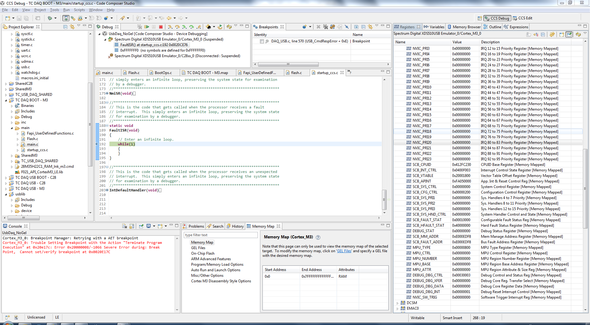
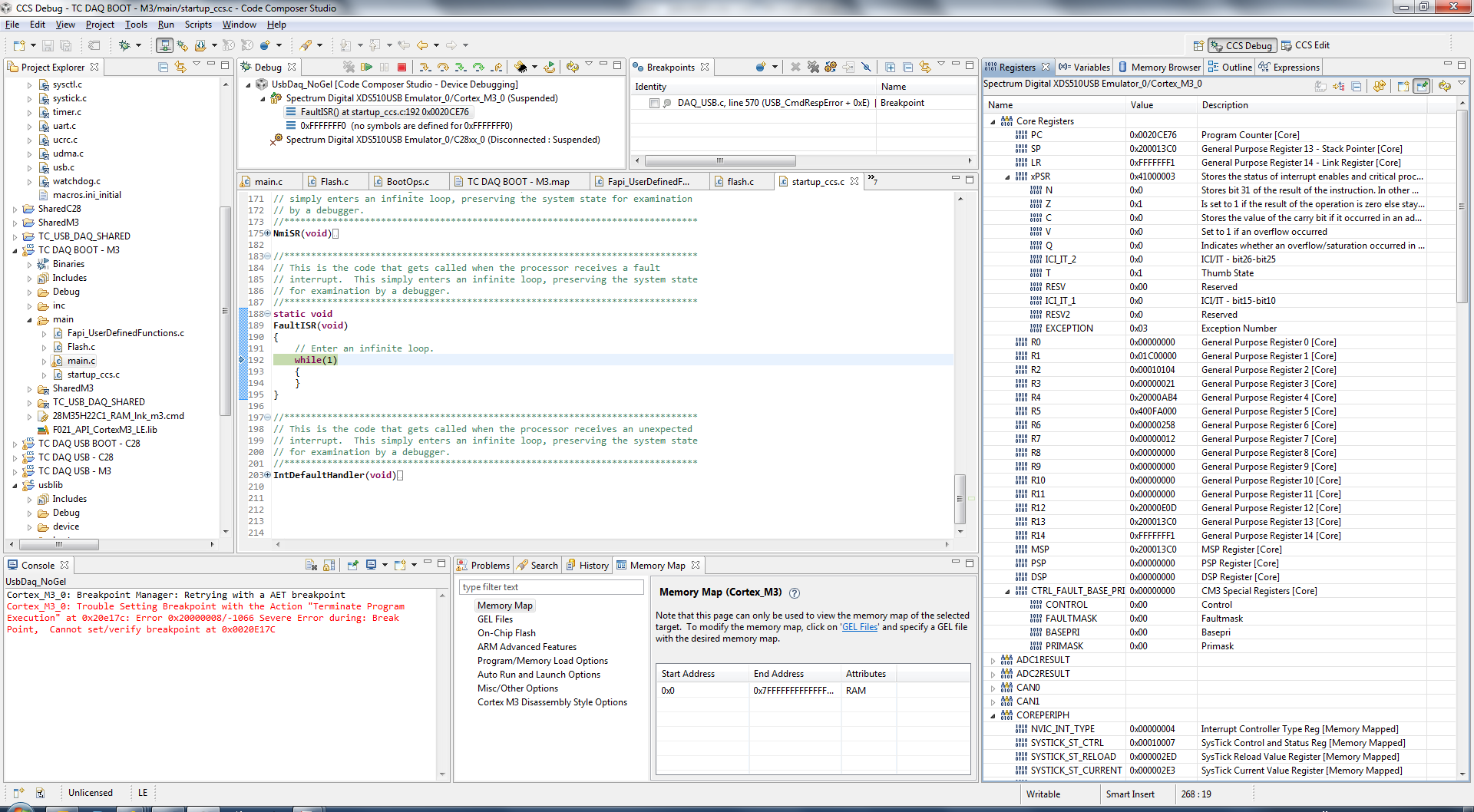
I would like to issue a software reset on the M3 and have the C28 and M3 both restart. I modified the blinky_dc example as a proof of concept, but it seems that only the M3 comes back from reset and hangs on IPCMtoCBootControlSystem(CBROM_MTOC_BOOTMODE_BOOT_FROM_FLASH);
Do I need to do something different to cause the c28 to come up correctly?
Thank you for your insights.
//########################################################################### // FILE: blinky.c // TITLE: blinky example. //########################################################################### // $TI Release: F28M36x Support Library v201 $ // $Release Date: Fri Jun 7 10:37:02 CDT 2013 $ //########################################################################### #include <string.h> #include "inc/hw_ints.h" #include "inc/hw_memmap.h" #include "inc/hw_nvic.h" #include "inc/hw_gpio.h" #include "inc/hw_types.h" #include "inc/hw_sysctl.h" #include "board_drivers/set_pinout_f28m36x.h" #include "driverlib/debug.h" #include "driverlib/flash.h" #include "driverlib/ipc.h" #include "driverlib/interrupt.h" #include "driverlib/sysctl.h" #include "driverlib/gpio.h" //***************************************************************************** // //! \addtogroup dual_example_list //! <h1>Blinky DC (blinky)</h1> //! //! Dual Core Blinky Example. This example demonstrates how to run a //! implement a standalone application on both cores. Due to an errate in //! the bootROM this example may not run correctly with the debugger connected. //! To run the example, program both cores with their respective project and //! then disconnect the debugger. Set SW3 switch 1 to the down position //! (disconnect TRSTn) as well as setting all 4 switches on SW1 to the down //! position. Cycle power and both LEDs should begin to blink. // //***************************************************************************** #ifdef _FLASH // These are defined by the linker (see device linker command file) extern unsigned long RamfuncsLoadStart; extern unsigned long RamfuncsRunStart; extern unsigned long RamfuncsLoadSize; #endif //***************************************************************************** // The error routine that is called if the driver library encounters an error. //***************************************************************************** #ifdef DEBUG void __error__(char *pcFilename, unsigned long ulLine) { } #endif //***************************************************************************** // // Blink LED3 //***************************************************************************** int main(void) { volatile unsigned long ulLoop; // Disable Protection HWREG(SYSCTL_MWRALLOW) = 0xA5A5A5A5; // Sets up PLL, M3 running at 100MHz and C28 running at 100MHz SysCtlClockConfigSet(SYSCTL_USE_PLL | (SYSCTL_SPLLIMULT_M & 0xA) | SYSCTL_SYSDIV_1 | SYSCTL_M3SSDIV_1 | SYSCTL_XCLKDIV_4); #ifdef _FLASH // Copy time critical code and Flash setup code to RAM // This includes the following functions: InitFlash(); // The RamfuncsLoadStart, RamfuncsLoadSize, and RamfuncsRunStart // symbols are created by the linker. Refer to the device .cmd file. memcpy(&RamfuncsRunStart, &RamfuncsLoadStart, (size_t)&RamfuncsLoadSize); // Call Flash Initialization to setup flash waitstates // This function must reside in RAM FlashInit(); #endif #ifdef _STANDALONE #ifdef _FLASH // Send boot command to allow the C28 application to begin execution IPCMtoCBootControlSystem(CBROM_MTOC_BOOTMODE_BOOT_FROM_FLASH); #else // Send boot command to allow the C28 application to begin execution IPCMtoCBootControlSystem(CBROM_MTOC_BOOTMODE_BOOT_FROM_RAM); #endif #endif // Enable clock supply for LED GPIOs SysCtlPeripheralEnable(LED_0_PERIPH); SysCtlPeripheralEnable(LED_1_PERIPH); // Give C28 control of Port C pin 6 GPIOPinConfigureCoreSelect(LED_0_BASE, LED_0_PIN, GPIO_PIN_C_CORE_SELECT); // Disable clock supply for the watchdog modules SysCtlPeripheralDisable(SYSCTL_PERIPH_WDOG1); SysCtlPeripheralDisable(SYSCTL_PERIPH_WDOG0); // Enable processor interrupts. IntMasterEnable(); // Set up the Pin for LED3 GPIOPinTypeGPIOOutput(LED_1_BASE, LED_1_PIN); GPIOPinWrite(LED_1_BASE, LED_1_PIN, ~0); // Loop forever while the timers run. unsigned int bigLoop = 5; while(bigLoop > 0) { // // Turn on the LED. // GPIOPinWrite(LED_1_BASE, LED_1_PIN, 0); // // Delay for a bit. // for(ulLoop = 0; ulLoop < 2000000; ulLoop++) { } // // Turn off the LED. // GPIOPinWrite(LED_1_BASE, LED_1_PIN, ~0); // // Delay for a bit. // for(ulLoop = 0; ulLoop < 2000000; ulLoop++) { } bigLoop--; } SysCtlReset(); }
looks like this issue is closed in mails - below is the solution.
call SysCtlHoldSubSystemInReset(1) - this will hold C28 under reset, next call SysCtlReset(), which resets M3. Now when M3 boot ROM runs it brings C28x out of reset when the system is ready, otherwise C28x comes out of reset and starts running C-boot ROM before system is ready.
Best Regards
Santosh
I have a similar situation with the F28M35. I intend to use the m3 to reset both cores as a means to jump from runtime code back to bootloader code.
Very infrequently, the M3 locks up in what appears to be a hard fault isr. I was able to connect with the emulator once. It looked like a systick exception had been declared before the hard fault isr was called as a result of trying to execute and undefined instruction.
I've been searching everywhere to see what could cause this. Before i do the soft reset, i call this:
SysTickWaitHundredthSec(6); // let usb finish
USB_DevBulkTerminate(); // end usb
SysTickTerminate();
IntMasterDisable(); // make sure all interrupts are disabled before jumping
SysCtlHoldSubSystemInReset(3); // hold in reset the C28 core and analog peripheral
SysCtlReset(); // reset the m3
while (1);
I can run 20000+ cycles with a test app before i get the hard fault. I am running out of ideas. I found some Cortex-M3 notes that say you should issue a "DSB" command to wait for the write buffer to drain. Is this necessary?
Can you think of any reason i could end up in a hard fault? It actually looked like the program counter was in args_main when the systick exception occurred. I have the default handler there. I guess the exception was escalated into a hard fault. This is confusing since the systick should not have been running at that point in the code. It just came out of a reset condition!
Here are screen shots of the registers at the time of the hard fault. I was running standalone for the test. Once i saw the lockup, i connected to the emulator, then connected to the m3 while making sure i didn't run gel files.
Looking back on it i wish i had a capture of the stack, but i don't. I know the xpsr that was thrown on the stack indicated ISRNUM = 0x3C.
i was finally able to fix this. It was a usb interrupt asserted while initializing the FlashApi. the
USB0DeviceIntHandler is flash and was called by a ramfunc -- Fapi_setupFlashStateMachine() -- as part of flash init.
It seems like disabling interrupts is the way to go since i can't put the entire usb lib in ram.