Hi,
I'm using DRV8301-HC-EVM Rev D and the F2806x ISO-controlCard to evaluate instaSPIN on one of our 24V PMSM motor.
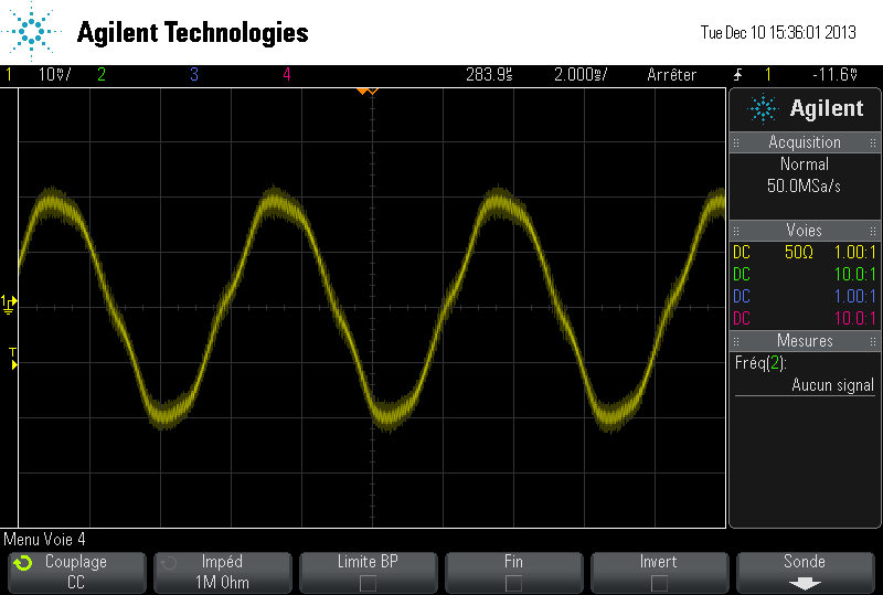
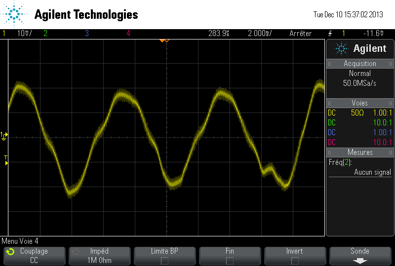
With the GUI pre-compiled program, my motor run a 4740RPM (nominal speed) until 18V when overmodulation is set to 1 and until 17V when overmodulation is set to 1.15 (and i can see a regular distorsion on the current waveform). Below this voltage, i can't reach 4740RPM but it is still running.
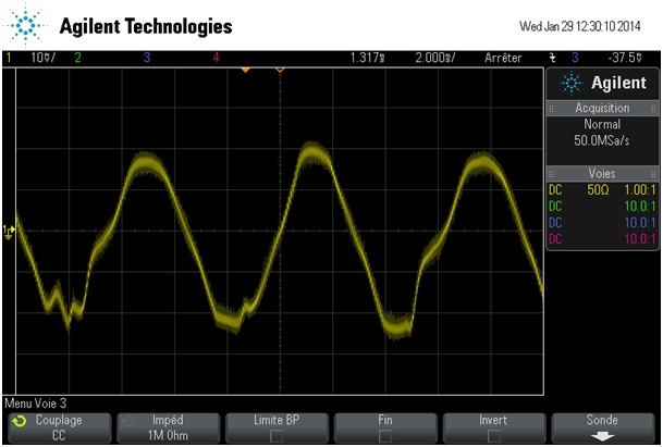
But with the lab example (lab03b), when the voltage reach 20V, there is some spurious distorsion on the current waveform :
At 21V :
At 19.8V :
I have also add 1us dead time but the problem was present before I add the dead time.
There is sometimes some little difference on RS and LS but with exactly the same, there is no change. I also adjust Kp and Ki to have exactly the same but there is no change.
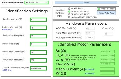
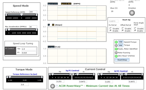
The GUI parameters are :
And now my user.h....
#ifndef _USER_H_
#define _USER_H_
/* --COPYRIGHT--,BSD
* Copyright (c) 2012, Texas Instruments Incorporated
* All rights reserved.
*
* Redistribution and use in source and binary forms, with or without
* modification, are permitted provided that the following conditions
* are met:
*
* * Redistributions of source code must retain the above copyright
* notice, this list of conditions and the following disclaimer.
*
* * Redistributions in binary form must reproduce the above copyright
* notice, this list of conditions and the following disclaimer in the
* documentation and/or other materials provided with the distribution.
*
* * Neither the name of Texas Instruments Incorporated nor the names of
* its contributors may be used to endorse or promote products derived
* from this software without specific prior written permission.
*
* THIS SOFTWARE IS PROVIDED BY THE COPYRIGHT HOLDERS AND CONTRIBUTORS "AS IS"
* AND ANY EXPRESS OR IMPLIED WARRANTIES, INCLUDING, BUT NOT LIMITED TO,
* THE IMPLIED WARRANTIES OF MERCHANTABILITY AND FITNESS FOR A PARTICULAR
* PURPOSE ARE DISCLAIMED. IN NO EVENT SHALL THE COPYRIGHT OWNER OR
* CONTRIBUTORS BE LIABLE FOR ANY DIRECT, INDIRECT, INCIDENTAL, SPECIAL,
* EXEMPLARY, OR CONSEQUENTIAL DAMAGES (INCLUDING, BUT NOT LIMITED TO,
* PROCUREMENT OF SUBSTITUTE GOODS OR SERVICES; LOSS OF USE, DATA, OR PROFITS;
* OR BUSINESS INTERRUPTION) HOWEVER CAUSED AND ON ANY THEORY OF LIABILITY,
* WHETHER IN CONTRACT, STRICT LIABILITY, OR TORT (INCLUDING NEGLIGENCE OR
* OTHERWISE) ARISING IN ANY WAY OUT OF THE USE OF THIS SOFTWARE,
* EVEN IF ADVISED OF THE POSSIBILITY OF SUCH DAMAGE.
* --/COPYRIGHT--*/
//! \file solutions/instaspin_foc/boards/drv8301kit_revD/f28x/f2806xF/src/user.h
//! \brief Contains the public interface for user initialization data for the CTRL, DRV, and EST modules
//!
//! (C) Copyright 2012, Texas Instruments, Inc.
// **************************************************************************
// the includes
// modules
#include "sw/modules/types/src/types.h"
#include "sw/modules/motor/src/motor.h"
#include "sw/modules/est/src/32b/est.h"
#include "sw/modules/est/src/est_states.h"
#include "sw/modules/est/src/est_Flux_states.h"
#include "sw/modules/est/src/est_Ls_states.h"
#include "sw/modules/est/src/est_Rs_states.h"
#include "sw/modules/ctrl/src/32b/ctrl_obj.h"
// platforms
#include "sw/modules/fast/src/32b/userParams.h"
//!
//!
//! \defgroup USER USER
//!
//@{
#ifdef __cplusplus
extern "C" {
#endif
// **************************************************************************
// the defines
//! \brief CURRENTS AND VOLTAGES
// **************************************************************************
//! \brief Defines the full scale frequency for IQ variable, Hz
//! \brief All frequencies are converted into (pu) based on the ratio to this value
//! \brief this value MUST be larger than the maximum speed that you are expecting from the motor
#define USER_IQ_FULL_SCALE_FREQ_Hz (200.0) // 800 Example with buffer for 8-pole 6 KRPM motor to be run to 10 KRPM with field weakening; Hz =(RPM * Poles) / 120
//! \brief Defines full scale value for the IQ30 variable of Voltage inside the system
//! \brief All voltages are converted into (pu) based on the ratio to this value
//! \brief WARNING: this value MUST be larger than the maximum value of any voltage calculated inside the control system otherwise the value can saturate and roll-over, causing an inaccurate value
//! \brief WARNING: this value is OFTEN greater than the maximum measured ADC value, especially with high Bemf motors operating at higher than rated speeds
//! \brief WARNING: if you know the value of your Bemf constant, and you know you are operating at a multiple speed due to field weakening, be sure to set this value higher than the expected Bemf voltage
//! \brief It is recommended to start with a value ~3x greater than the USER_ADC_FULL_SCALE_VOLTAGE_V and increase to 4-5x if scenarios where a Bemf calculation may exceed these limits
//! \brief This value is also used to calculate the minimum flux value: USER_IQ_FULL_SCALE_VOLTAGE_V/USER_EST_FREQ_Hz/0.7
#define USER_IQ_FULL_SCALE_VOLTAGE_V (42.0) // 42.0 Example for drv8301 typical usage and the Anaheim motor
//! \brief Defines the maximum voltage at the input to the AD converter
//! \brief The value that will be represtented by the maximum ADC input (3.3V) and conversion (0FFFh)
//! \brief Hardware dependent, this should be based on the voltage sensing and scaling to the ADC input
#define USER_ADC_FULL_SCALE_VOLTAGE_V (66.32) // 66.32 drv8301_revd voltage scaling
//! \brief Defines the voltage scale factor for the system
//! \brief Compile time calculation for scale factor (ratio) used throughout the system
#define USER_VOLTAGE_SF ((float_t)((USER_ADC_FULL_SCALE_VOLTAGE_V)/(USER_IQ_FULL_SCALE_VOLTAGE_V)))
//! \brief Defines the full scale current for the IQ variables, A
//! \brief All currents are converted into (pu) based on the ratio to this value
//! \brief WARNING: this value MUST be larger than the maximum current readings that you are expecting from the motor or the reading will roll over to 0, creating a control issue
#define USER_IQ_FULL_SCALE_CURRENT_A (41.25) // 41.25 Example for drv8301_revd typical usage
//! \brief Defines the maximum current at the AD converter
//! \brief The value that will be represtented by the maximum ADC input (3.3V) and conversion (0FFFh)
//! \brief Hardware dependent, this should be based on the current sensing and scaling to the ADC input
#define USER_ADC_FULL_SCALE_CURRENT_A (82.5) // 82.5 drv8301_revd current scaling
//! \brief Defines the current scale factor for the system
//! \brief Compile time calculation for scale factor (ratio) used throughout the system
#define USER_CURRENT_SF ((float_t)((USER_ADC_FULL_SCALE_CURRENT_A)/(USER_IQ_FULL_SCALE_CURRENT_A)))
//! \brief Defines the number of current sensors used
//! \brief Defined by the hardware capability present
//! \brief May be (2) or (3)
#define USER_NUM_CURRENT_SENSORS (3) // 3 Preferred setting for best performance across full speed range, allows for 100% duty cycle
//! \brief Defines the number of voltage (phase) sensors
//! \brief Must be (3)
#define USER_NUM_VOLTAGE_SENSORS (3) // 3 Required
//! \brief ADC current offsets for A, B, and C phases
//! \brief One-time hardware dependent, though the calibration can be done at run-time as well
//! \brief After initial board calibration these values should be updated for your specific hardware so they are available after compile in the binary to be loaded to the controller
#define I_A_offset (0.991140902)//(0.9939797521)
#define I_B_offset (0.9958643317)//(1.014363647)
#define I_C_offset (1.009294033)//(1.005615234)
//! \brief ADC voltage offsets for A, B, and C phases
//! \brief One-time hardware dependent, though the calibration can be done at run-time as well
//! \brief After initial board calibration these values should be updated for your specific hardware so they are available after compile in the binary to be loaded to the controller
#define V_A_offset (0.291772902)//(0.5020679235)
#define V_B_offset (0.2910662293)//(0.4977650046)
#define V_C_offset (0.2902891636)//(0.4986107945)
//! \brief CLOCKS & TIMERS
// **************************************************************************
//! \brief Defines the system clock frequency, MHz
#define USER_SYSTEM_FREQ_MHz (90.0)
//! \brief Defines the Pulse Width Modulation (PWM) frequency, kHz
//! \brief PWM frequency can be set directly here up to 30 KHz safely (60 KHz MAX in some cases)
//! \brief For higher PWM frequencies (60 KHz+ typical for low inductance, high current ripple motors) it is recommended to use the ePWM hardware
//! \brief and adjustable ADC SOC to decimate the ADC conversion done interrupt to the control system, or to use the software Que example.
//! \brief Otherwise you risk missing interrupts and disrupting the timing of the control state machine
#define USER_PWM_FREQ_kHz (20.0)// (45.0) //30.0 Example, 8.0 - 30.0 KHz typical; 45-80 KHz may be required for very low inductance, high speed motors
//! \brief Defines the maximum Voltage vector (Vs) magnitude allowed. This value sets the maximum magnitude for the output of the
//! \brief Id and Iq PI current controllers. The Id and Iq current controller outputs are Vd and Vq.
//! \brief The relationship between Vs, Vd, and Vq is: Vs = sqrt(Vd^2 + Vq^2). In this FOC controller, the
//! \brief Vd value is set equal to USER_MAX_VS_MAG*USER_VD_MAG_FACTOR. Vq = sqrt(USER_MAX_VS_MAG^2 - Vd^2).
//! \brief Set USER_MAX_VS_MAG = 1.0 for a pure sinewave with a peak at SQRT(3)/2 = 86.6% duty cycle. No current reconstruction is needed for this scenario.
//! \brief Set USER_MAX_VS_MAG = 2/SQRT(3) = 1.1547 for a pure sinewave with a peak at 100% duty cycle. Current reconstruction will be needed for this scenario (Lab10a-x).
//! \brief Set USER_MAX_VS_MAG = 4/3 = 1.3333 to create a trapezoidal voltage waveform. Current reconstruction will be needed for this scenario (Lab10a-x).
//! \brief For space vector over-modulation, see lab 10 for details on system requirements that will allow the SVM generator to go all the way to trapezoidal.
#define USER_MAX_VS_MAG_PU (1.0) // Set to 1.0 if a current reconstruction technique is not used. Look at the module svgen_current in lab10a-x for more info.
//! \brief Defines the Pulse Width Modulation (PWM) period, usec
//! \brief Compile time calculation
#define USER_PWM_PERIOD_usec (1000.0/USER_PWM_FREQ_kHz)
//! \brief Defines the Interrupt Service Routine (ISR) frequency, Hz
//!
#define USER_ISR_FREQ_Hz ((float_t)USER_PWM_FREQ_kHz * 1000.0 / (float_t)USER_NUM_PWM_TICKS_PER_ISR_TICK)
//! \brief Defines the Interrupt Service Routine (ISR) period, usec
//!
#define USER_ISR_PERIOD_usec (USER_PWM_PERIOD_usec * (float_t)USER_NUM_PWM_TICKS_PER_ISR_TICK)
//! \brief DECIMATION
// **************************************************************************
//! \brief Defines the number of pwm clock ticks per isr clock tick
//! Note: Valid values are 1, 2 or 3 only
#define USER_NUM_PWM_TICKS_PER_ISR_TICK 2//(3)
//! \brief Defines the number of isr ticks (hardware) per controller clock tick (software)
//! \brief Controller clock tick (CTRL) is the main clock used for all timing in the software
//! \brief Typically the PWM Frequency triggers (can be decimated by the ePWM hardware for less overhead) an ADC SOC
//! \brief ADC SOC triggers an ADC Conversion Done
//! \brief ADC Conversion Done triggers ISR
//! \brief This relates the hardware ISR rate to the software controller rate
//! \brief Typcially want to consider some form of decimation (ePWM hardware, CURRENT or EST) over 16KHz ISR to insure interrupt completes and leaves time for background tasks
#define USER_NUM_ISR_TICKS_PER_CTRL_TICK (1) // 2 Example, oontroller clock rate (CTRL) runs at PWM / 2; ex 30 KHz PWM, 15 KHz control
//! \brief Defines the number of controller clock ticks per current controller clock tick
//! \brief Relationship of controller clock rate to current controller (FOC) rate
#define USER_NUM_CTRL_TICKS_PER_CURRENT_TICK (1) // 1 Typical, Forward FOC current controller (Iq/Id/IPARK/SVPWM) runs at same rate as CTRL.
//! \brief Defines the number of controller clock ticks per estimator clock tick
//! \brief Relationship of controller clock rate to estimator (FAST) rate
//! \brief Depends on needed dynamic performance, FAST provides very good results as low as 1 KHz while more dynamic or high speed applicatons may require up to 15 KHz
#define USER_NUM_CTRL_TICKS_PER_EST_TICK (1) // 1 Typical, FAST estimator runs at same rate as CTRL;
//! \brief Defines the number of controller clock ticks per speed controller clock tick
//! \brief Relationship of controller clock rate to speed loop rate
#define USER_NUM_CTRL_TICKS_PER_SPEED_TICK (15) // 15 Typical to match PWM, ex: 15KHz PWM, controller, and current loop, 1KHz speed loop
//! \brief Defines the number of controller clock ticks per trajectory clock tick
//! \brief Relationship of controller clock rate to trajectory loop rate
//! \brief Typically the same as the speed rate
#define USER_NUM_CTRL_TICKS_PER_TRAJ_TICK (15) // 15 Typical to match PWM, ex: 10KHz controller & current loop, 1KHz speed loop, 1 KHz Trajectory
//! \brief Defines the controller frequency, Hz
//! \brief Compile time calculation
#define USER_CTRL_FREQ_Hz (uint_least32_t)(USER_ISR_FREQ_Hz/USER_NUM_ISR_TICKS_PER_CTRL_TICK)
//! \brief Defines the estimator frequency, Hz
//! \brief Compile time calculation
#define USER_EST_FREQ_Hz (uint_least32_t)(USER_CTRL_FREQ_Hz/USER_NUM_CTRL_TICKS_PER_EST_TICK)
//! \brief Defines the trajectory frequency, Hz
//! \brief Compile time calculation
#define USER_TRAJ_FREQ_Hz (uint_least32_t)(USER_CTRL_FREQ_Hz/USER_NUM_CTRL_TICKS_PER_TRAJ_TICK)
//! \brief Defines the controller execution period, usec
//! \brief Compile time calculation
#define USER_CTRL_PERIOD_usec (USER_ISR_PERIOD_usec * USER_NUM_ISR_TICKS_PER_CTRL_TICK)
//! \brief Defines the controller execution period, sec
//! \brief Compile time calculation
#define USER_CTRL_PERIOD_sec ((float_t)USER_CTRL_PERIOD_usec/(float_t)1000000.0)
//! \brief LIMITS
// **************************************************************************
//! \brief Defines the maximum negative current to be applied in Id reference
//! \brief Used in field weakening only, this is a safety setting (e.g. to protect against demagnetizaton)
//! \brief User must also be aware that overall current magnitude [sqrt(Id^2 + Iq^2)] should be kept below any machine design specifications
#define USER_MAX_NEGATIVE_ID_REF_CURRENT_A (-2.0) // -2.0 Example, adjust to meet safety needs of your motor
//! \brief Defines the low speed limit for the flux integrator, pu
//! \brief This is the speed range (CW/CCW) at which the ForceAngle object is active, but only if Enabled
//! \brief Outside of this speed - or if Disabled - the ForcAngle will NEVER be active and the angle is provided by FAST only
#define USER_ZEROSPEEDLIMIT (0.002) // 0.002 pu, 1-5 Hz typical; Hz = USER_ZEROSPEEDLIMIT * USER_IQ_FULL_SCALE_FREQ_Hz
//! \brief Defines the force angle frequency, Hz
//! \brief Frequency of stator vector rotation used by the ForceAngle object
//! \brief Can be positive or negative
#define USER_FORCE_ANGLE_FREQ_Hz (1.0) // 1.0 Typical force angle start-up speed
//! \brief Defines the maximum current slope for Id trajectory during EPL mode
//! \brief For Induction motors only, controls how fast Id input can change under EPL control
#define USER_MAX_CURRENT_SLOPE_EPL (0.3*USER_MOTOR_RES_EST_CURRENT/USER_IQ_FULL_SCALE_CURRENT_A/USER_TRAJ_FREQ_Hz) // 0.3*RES_EST_CURRENT / IQ_FULL_SCALE_CURRENT / TRAJ_FREQ Typical to produce 1-sec rampup/down
//! \brief Defines the starting maximum acceleration AND deceleration for the speed profiles, Hz/s
//! \brief Updated in run-time through user functions
//! \brief Inverter, motor, inertia, and load will limit actual acceleration capability
#define USER_MAX_ACCEL_Hzps (20.0) // 20.0 Default
//! \brief Defines maximum acceleration for the estimation speed profiles, rad/sec^2
//! \brief Only used during Motor ID (commission)
#define USER_MAX_ACCEL_EST_Hzps (5.0) // 5.0 Default, don't change
//! \brief Defines the maximum current slope for Id trajectory during estimation
#define USER_MAX_CURRENT_SLOPE (USER_MOTOR_RES_EST_CURRENT/USER_IQ_FULL_SCALE_CURRENT_A/USER_TRAJ_FREQ_Hz) // USER_MOTOR_RES_EST_CURRENT/USER_IQ_FULL_SCALE_CURRENT_A/USER_TRAJ_FREQ_Hz Default, don't change
//! \brief Defines the fraction of IdRated to use during rated flux estimation
//!
#define USER_IDRATED_FRACTION_FOR_RATED_FLUX (0.5) // 0.5 Default, don't change
//! \brief Defines the fraction of IdRated to use during inductance estimation
//!
#define USER_IDRATED_FRACTION_FOR_L_IDENT (0.5) // 0.5 Default, don't change
//! \brief Defines the IdRated delta to use during estimation
//!
#define USER_IDRATED_DELTA (0.0001) // 0.0001 Default, don't change
//! \brief Defines the fraction of SpeedMax to use during inductance estimation
//!
#define USER_SPEEDMAX_FRACTION_FOR_L_IDENT (1.0) // 1.0 Default, don't change
//! \brief Defines flux fraction to use during inductance identification
//!
#define USER_FLUX_FRACTION (1.0) // 1.0 Default, don't change
//! \brief Defines the EPL (Efficient Partial Load) gain for computing Id reference
//! \brief Induction motors only
#define USER_EPL_GAIN (1.0) // 1.0 Default, don't change
//! \brief Defines the R/L estimation frequency, Hz
//! \brief User higher values for low inductance motors and lower values for higher inductance
//! \brief motors. The values can range from 100 to 300 Hz.
#define USER_R_OVER_L_EST_FREQ_Hz (300) // 300 Default
//! \brief POLES
// **************************************************************************
//! \brief Defines the analog voltage filter pole location, Hz
//! \brief Must match the hardware filter for Vph
#define USER_VOLTAGE_FILTER_POLE_Hz (335.648) // 335.648, value for drv8301_revd hardware
//! \brief Defines the analog voltage filter pole location, rad/s
//! \brief Compile time calcuation from Hz to rad/s
#define USER_VOLTAGE_FILTER_POLE_rps (2.0 * MATH_PI * USER_VOLTAGE_FILTER_POLE_Hz)
//! \brief Defines the software pole location for the voltage and current offset estimation, rad/s
//! \brief Should not be changed from default of (20.0)
#define USER_OFFSET_POLE_rps (20.0) // 20.0 Default, do not change
//! \brief Defines the software pole location for the flux estimation, rad/s
//! \brief Should not be changed from default of (100.0)
#define USER_FLUX_POLE_rps (100.0) // 100.0 Default, do not change
//! \brief Defines the software pole location for the direction filter, rad/s
#define USER_DIRECTION_POLE_rps (6.0) // 6.0 Default, do not change
//! \brief Defines the software pole location for the speed control filter, rad/s
#define USER_SPEED_POLE_rps (100.0) // 100.0 Default, do not change
//! \brief Defines the software pole location for the DC bus filter, rad/s
#define USER_DCBUS_POLE_rps (100.0) // 100.0 Default, do not change
//! \brief Defines the convergence factor for the estimator
//! \brief Do not change from default for FAST
#define USER_EST_KAPPAQ (1.5) // 1.5 Default, do not change
// **************************************************************************
// end the defines
//! \brief USER MOTOR & ID SETTINGS
// **************************************************************************
//! \brief Define each motor with a unique name and ID number
// BLDC & SMPM motors
#define Estun_EMJ_04APB22 101
#define Anaheim_BLY172S 102
#define My_Motor 104
#define hobby_3p5T 105
#define hobby_4p5T 106
#define small_hobby 107
#define teknic_2310P 108
#define hobbywing_ezrun_8p5T 109
#define eflite_helicopter_420 110
#define Bodine_34B3FEBL 114
#define Pittman_elcom_5233B599 115
#define medical_instrument 117
// IPM motors
// If user provides separate Ls-d, Ls-q
// else treat as SPM with user or identified average Ls
#define Belt_Drive_Washer_IPM 201
// ACIM motors
#define Marathon_5K33GN2A 301
//! \brief Uncomment the motor which shold be included at compile
//! \brief These motor ID settings and motor parameters are then available to be used by the control system
//! \brief Once your ideal settings and parameters are identified update the motor section here so it is available in the binary code
//#define USER_MOTOR Estun_EMJ_04APB22
//#define USER_MOTOR Anaheim_BLY172S
//#define USER_MOTOR hobby_3p5T
//#define USER_MOTOR hobby_4p5T
#define USER_MOTOR My_Motor
//#define USER_MOTOR small_hobby
//#define USER_MOTOR Belt_Drive_Washer_IPM
//#define USER_MOTOR Marathon_5K33GN2A
//#define USER_MOTOR teknic_2310P
//#define USER_MOTOR hobbywing_ezrun_8p5T
//#define USER_MOTOR eflite_helicopter_420
//#define USER_MOTOR Bodine_34B3FEBL
//#define USER_MOTOR Pittman_elcom_5233B599
//#define USER_MOTOR medical_instrument
#if (USER_MOTOR == Estun_EMJ_04APB22) // Name must match the motor #define
#define USER_MOTOR_TYPE MOTOR_Type_Pm // Motor_Type_Pm (All Synchronous: BLDC, PMSM, SMPM, IPM) or Motor_Type_Induction (Asynchronous ACI)
#define USER_MOTOR_NUM_POLE_PAIRS (4) // PAIRS, not total poles. Used to calculate user RPM from rotor Hz only
#define USER_MOTOR_Rr (NULL) // Induction motors only, else NULL
#define USER_MOTOR_Rs (2.303403) // Identified phase to neutral resistance in a Y equivalent circuit (Ohms, float)
#define USER_MOTOR_Ls_d (0.008464367) // For PM, Identified average stator inductance (Henry, float)
#define USER_MOTOR_Ls_q (0.008464367) // For PM, Identified average stator inductance (Henry, float)
#define USER_MOTOR_RATED_FLUX (0.38) // Identified TOTAL flux linkage between the rotor and the stator (V/Hz)
#define USER_MOTOR_MAGNETIZING_CURRENT (NULL) // Induction motors only, else NULL
#define USER_MOTOR_RES_EST_CURRENT (1.0) // During Motor ID, maximum current (Amperes, float) used for Rs estimation, 10-20% rated current
#define USER_MOTOR_IND_EST_CURRENT (-1.0) // During Motor ID, maximum current (negative Amperes, float) used for Ls estimation, use just enough to enable rotation
#define USER_MOTOR_MAX_CURRENT (3.82) // CRITICAL: Used during ID and run-time, sets a limit on the maximum current command output of the provided Speed PI Controller to the Iq controller
#define USER_MOTOR_FLUX_EST_FREQ_Hz (20.0) // During Motor ID, maximum commanded speed (Hz, float), ~10% rated
#elif (USER_MOTOR == My_Motor)
#define USER_MOTOR_TYPE MOTOR_Type_Pm
#define USER_MOTOR_NUM_POLE_PAIRS (2)
#define USER_MOTOR_Rr (NULL)
#define USER_MOTOR_Rs (0.0561226)//(0.1281301)//(0.1076983)
#define USER_MOTOR_Ls_d (0.0001031196)//(0.0002003067)//(0.000254845)
#define USER_MOTOR_Ls_q (0.0001031196)//(0.0002003067)//(0.000254845)
#define USER_MOTOR_RATED_FLUX (0.0490102)//(0.07455059)
#define USER_MOTOR_MAGNETIZING_CURRENT (NULL)
#define USER_MOTOR_RES_EST_CURRENT (2)
#define USER_MOTOR_IND_EST_CURRENT (-2)
#define USER_MOTOR_MAX_CURRENT (15.0)
#define USER_MOTOR_FLUX_EST_FREQ_Hz (20.0)
#else
#error No motor type specified
#endif
#ifndef USER_MOTOR
#error Motor is not defined in user.h
#endif
#ifndef USER_MOTOR_TYPE
#error The motor type is not defined in user.h
#endif
#ifndef USER_MOTOR_NUM_POLE_PAIRS
#error Number of motor pole pairs is not defined in user.h
#endif
#ifndef USER_MOTOR_Rr
#error The rotor resistance is not defined in user.h
#endif
#ifndef USER_MOTOR_Rs
#error The stator resistance is not defined in user.h
#endif
#ifndef USER_MOTOR_Ls_d
#error The direct stator inductance is not defined in user.h
#endif
#ifndef USER_MOTOR_Ls_q
#error The quadrature stator inductance is not defined in user.h
#endif
#ifndef USER_MOTOR_RATED_FLUX
#error The rated flux of motor is not defined in user.h
#endif
#ifndef USER_MOTOR_MAGNETIZING_CURRENT
#error The magnetizing current is not defined in user.h
#endif
#ifndef USER_MOTOR_RES_EST_CURRENT
#error The resistance estimation current is not defined in user.h
#endif
#ifndef USER_MOTOR_IND_EST_CURRENT
#error The inductance estimation current is not defined in user.h
#endif
#ifndef USER_MOTOR_MAX_CURRENT
#error The maximum current is not defined in user.h
#endif
#ifndef USER_MOTOR_FLUX_EST_FREQ_Hz
#error The flux estimation frequency is not defined in user.h
#endif
// **************************************************************************
// the functions
//! \brief Sets the user parameter values
//! \param[in] pUserParams The pointer to the user param structure
extern void USER_setParams(USER_Params *pUserParams);
#ifdef __cplusplus
}
#endif // extern "C"
//@} // ingroup
#endif // end of _USER_H_ definition
There must be a difference but i can't find it because we don't have the source parameter of the GUI application.
Thanks if someone can help me.
Regards.
Emmanuel