Other Parts Discussed in Thread: SYSBIOS
I am working on speeding up my current loop, done in an ISR, and am having difficulty figuring out what is wrong. In my SYSBIOS program on a 28335, I am triggering an HWI with every ADC conversion and posting a SWI to go to the correct sequence, like so.
void ADC_INT_ISR(void) // PIE1.6 @ 0x000D4A ADCINT (ADC)
{
PieCtrlRegs.PIEACK.all = PIEACK_GROUP1; // Must acknowledge the PIE group
if (AdcRegs.ADCST.bit.INT_SEQ1 == 1) // If Sequencer #1 triggered the interrupt
{
AdcRegs.ADCST.bit.INT_SEQ1_CLR = 1; // Clear the interrupt in the ADC registers
Swi_post(ADCSEQ1_swi); // Post the ADC Sequencer #1 SWI
}
if (AdcRegs.ADCST.bit.INT_SEQ2 == 1) // If Sequencer #2 triggered the interrupt
{
AdcRegs.ADCST.bit.INT_SEQ2_CLR = 1; // Clear the interrupt in the ADC registers
Swi_post(ADCSEQ2_swi); // Post the ADC Sequencer #2 SWI
}
} // end of ADC_INT_ISR()
Once in my SWI, I check the phase that triggered the conversion,
if (EPwm1Regs.ETFLG.bit.SOCA == 1) // conversion triggered by PWM phase A
{
EPwm1Regs.ETCLR.bit.SOCA = 1; // clear the flag denoting SOC started by phase A
PWMState = STATE_EOC_PHASE_A; // Denote that the PWM module state is such that phase A conversion just completed
}
then check that this phase matches the PWM phase that just ended.
if (AdcRegs.ADCASEQSR.bit.SEQ1_STATE == STATE_EOC_PHASE_A && PWMState == STATE_EOC_PHASE_A) // Measurements corresponding to phase A just completed
{
now is where my trouble is. I am trying to do this for all three phases and have the program is operating smoothly, as long as my PWM frequency is 6 kHz or less. If I try to go any higher than that, the routine takes too long and I can't finish the loop in time.
As it stands, the program is written in floating point and the current calculation starts with this equation.
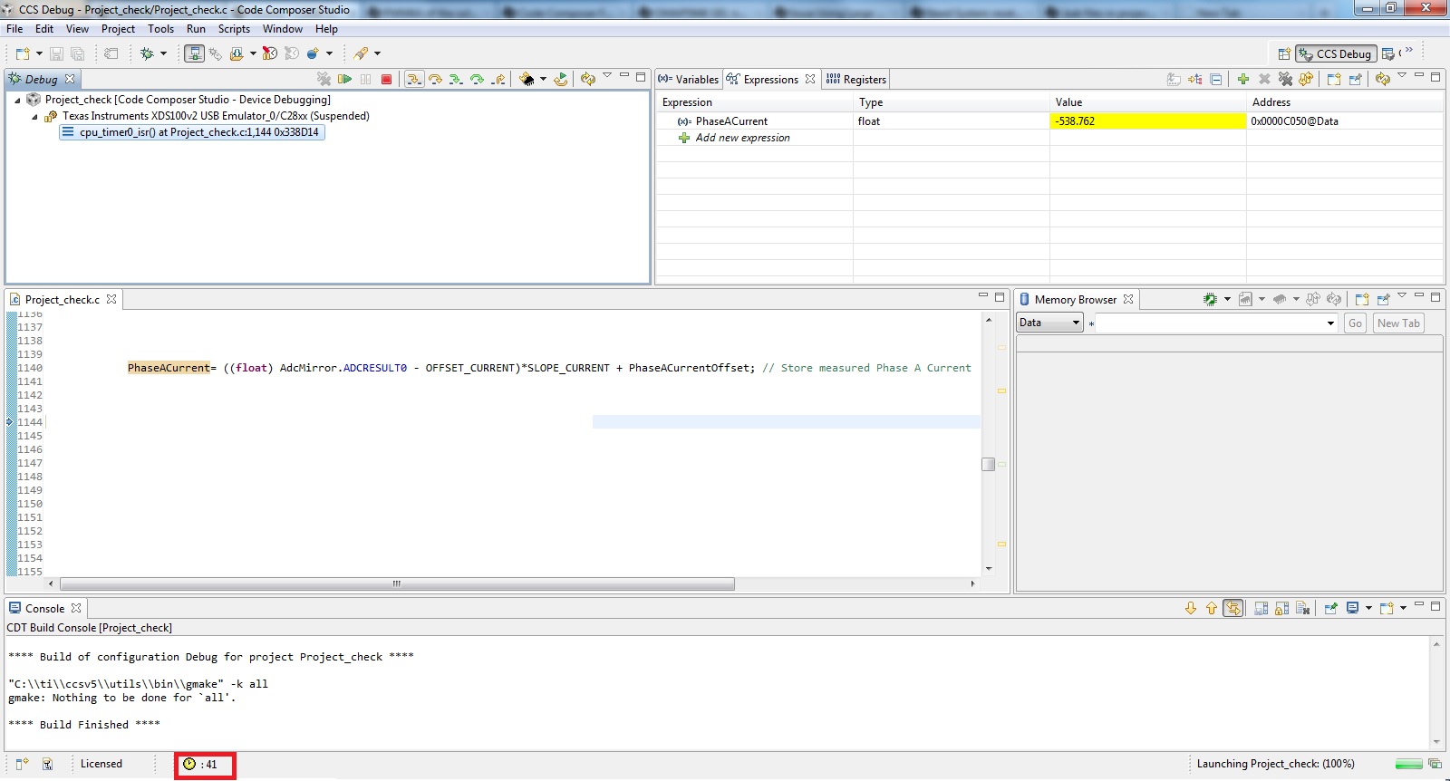
Measured.PhaseACurrent = ((float) AdcMirror.ADCRESULT0 - OFFSET_CURRENT)*SLOPE_CURRENT + PhaseACurrentOffset; // Store measured Phase A Current
I know floating point math is slow, and according to the clock ticks at the bottom of the CCS debug window, this line takes about 2,200 ticks.
So I tried to re-write this in IQ math without having to change too much of the rest of the program. I rewrote the line like this, and the code takes around 3,000 ticks to complete this calculation.
Measured.PhaseACurrent=_IQ19toF((_IQmpy((_IQ19(AdcMirror.ADCRESULT0) - _IQ19(OFFSET_CURRENT)), _IQ19(SLOPE_CURRENT)) + _IQ19(PhaseACurrentOffset)));
I have included the fpu32.lib like so:
IQmathTables : > IQTABLES, PAGE = 1, TYPE = NOLOAD
IQmathTables2 : > IQTABLES2, PAGE = 1, TYPE = NOLOAD
{
IQmath_fpu32.lib<IQNexpTable.obj> (IQmathTablesRam)
}
IQmathTablesRam : load = L27SARAM, PAGE = 1
IQmath : load = L27SARAM, PAGE = 1
}
and set float_support=fpu32
The variables this equation is using are defined as:
#define OFFSET_CURRENT 2048 // Offset of current measurement, in digits
#define SLOPE_CURRENT -0.300480769 // Slope of current measurement, in Amps per digit
extern float PhaseACurrentOffset =0 ; // current offset for phase A, in Amps
Is there something I am doing wrong? I was under the impression that IQ math was much fast than float, but is this not necessarily the case when having to convert in the equation?