This thread has been locked.

If you have a related question, please click the "Ask a related question" button in the top right corner. The newly created question will be automatically linked to this question.

problems with the transmission of pwm synchronization pulse between concerto cards as noise increases

Other Parts Discussed in Thread: LM339

Hi all, 

I am using two concerto control cards to control two DC/AC converters. I use the SYNCO/SYNCI GPIOs to synchronize the PWM generation of two concerto cards and the synchronization works perfectly as long as the DC voltage is under 400 V. However, if the DC voltage grows beyond that value, the synchronization start failing and current peaks occurs in the converter controlled by the slave control card.I checked that the sync pulse was very affected by external noise by displaying it with my scope.

To solve that problem I have tried different options to transmit the sync pulse. First, I connect the synci and synco GPIOs directly using different type of wire (unifilar, multifilar and coaxial) then I used optic fiber to transmit the pulse. None of them worked. I must indicate that the control cards are very close to the converters and everything is placed inside of a wall mounted enclosure. In fact, the loss of synchronization doesn't happen if the control cards are placed outside the metallic enclosure. Unfortunately, their place is inside the enclosure. So,  can anyone give some tips to reduce the impact of the noise on the sync pulse?. What could I do to make the sync signal more robust to noise? Any ideas are welcome ;-).

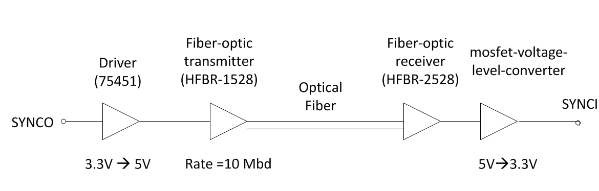
I attach a schema of my system with the aim to make my exposition clearer:

Each concerto card is connected to a PCB by using a DIMM100 connector. The PCB is quite simple. it contains an analog part that adapts the voltage levels driven by the current and voltage sensors to the range [3.3V-0V] and a digital part that protects the converter from undesired PWM outputs that could happen during the CCS debugging process (mainly during the loading process).

Thanks in advance, 

Juan.

  • Hi,

    We did once face similar issue, in our case it was introduced by ground noise. So we used an EMI filter and also connected the power ground to the metal cabinet for getting access to Earthing.

    Regards,

    Gautam

  • Hi Gautam, thanks for your reply.

    I have some questions. How did you find out that your system was suffering ground noise? What kind of tests did you carry out? It would be great to identify the problem before making any decision.

    I also have some doubts about the possible solution you suggest (I am a newbie to EMI issues so please correct me if I am wrong). First of all, I must say that the power ground of my system is already connected to Earthing (the power ground and Earth are internally connected by the converter). With regards to the EMI filters, to my best knowledge EMI filters are used to reduce the conducted EMI (src: http://www.ti.com/lit/an/snva489c/snva489c.pdf). As I mentioned in my previous post, the sync problem only appears when the PCB is inside the cabinet what suggests me that the problem is related to radiated EMI rather than conducted. Do your agree? Besides,  it seems that these these filters are mainly applied to DC/DC topologies rather than DC/AC  ones  (I couldn't find info about their application to DC/AC topologies). Then, in case of using the EMI filter, where do your suggest to place it in my system?.

    Finally, I am curious to know if you were working with DC/AC converters when you found the issue you mentioned in your answer. Could you give me such info?

    Thanks in advance.

    Regards,

    Juan

  • Hi,

    How did you find out that your system was suffering ground noise?

    My ADC signals were getting heavily corrupted; after going through numerous posts I shortlisted the noise was due to ground noise. My converter was a DC/DC.

    Also the effect by introducing EMI filters was not much but had some. Proper earthing the equipment was the solution.

    Juan, will get back to you with detailed info soon. Its time for me to leave :)

    Regards,

    Gautam

  • Thanks Gautam,

    I look forward to receiving that info ;-).

    Regards,

    Juan

  • GM Juan,

    Also, by using LPFs and notch filters our circuit is now noise free :)

    But we're still working on the power supply part to eliminate all the noises on the ground level.

    I checked that the sync pulse was very affected by external noise by displaying it with my scope.

    How do you feed this sync signal to the other controller?

    Regards,

    Gautam

  • Hi Gautam,

    I tried several options. First, I directly connected the SYNCO input (GPIO33) and the SYNCI (GPIO32) through the two PCBs. Each PCB provides SYNCI/SYNCO connectors which are connected to the respective pins of the DIMM100 connector associated to GPIO32/33. I used a PVC insulated solid wire to connect both GPIOs. It didn't work. Then, I tried to connect both GPIOs through their MUX connectors. It didn't work either. Afterwards, I replaced the solid wire with a coaxial cable ( the shield was connected to GND) and carried out the two mentioned alternatives of connection. It failed again. Finally, I gave optic fiber a try and it worked (but only outside the cabinet). I attach a sketch of the connection scheme:

    In the master side, I adapt the voltage level of the synco pulse to the optic transmitter. In the slave side, I convert the voltage level from 5V to 3.3V by using a MOSFETr (2N7000) which drives its output to the SYNCI GPIO.

    Thank for your help, Gautam ;-)

    Regards,

    Juan.

  • Juan, feels like a case of EMI radiation for sure! Check this wonderfully composed doc on EMI:

    http://www.silabs.com/Marcom%20Documents/Resources/EMI-guide.pdf

    Regards,

    Gautam

  • Thanks Gautam,

    great guide for a beginner like me! I will try to follow the recommendations included in the doc.

    I will keep you up to date with any progress.

    Thank you again for your help.

    Regards,

    Juan

  • I will keep you up to date with any progress.

    Yes, do keep me updated on the same.

    Thank you again for your help.

    No problem, I'm here to help you mate.

    Regards,

    Gautam

  • Hi again, 

    I have good news. I finally was able to run my controller inside the metal cabinet. I isolated my PCB from the external EMI placing it in a metal box and I achieved to run the controller perfectly. Once I checked this solution worked, I tried to make it works without the metal box.  I replaced the metal box with a metal sheet to separate the PCB and the converter. I put this sheet between them in order to reduce the noise induced by the converter into my PCB. Surprisingly, it worked too so I didn't even need the metal box in the end.

    Regards, Juan.

  • Hi Juan,

    That's a fantastic news. Please close this thread by verifying the answer so that others can take advantage of this thread too.

    Good Luck and Regards,

    Gautam

  • Hi guys,


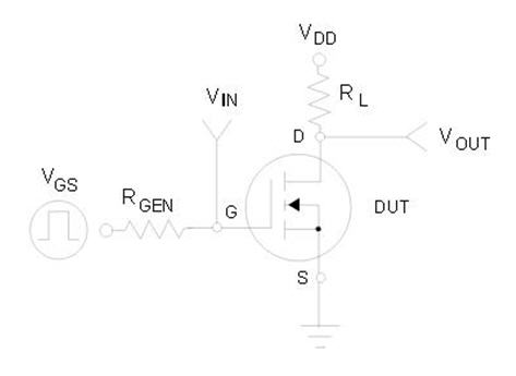
    I've built the set up Juan was describing, and I can see the SYNCO pulse at the receiver side in the drain of  2N7000. It is inverted, and this is good because I wanna use the SYNC together with an enable signal and if the optical link is disconnected, in the drain I will get a '0' logic which is exactly what I need. The question is how should I invert the SYNCO at the transmission side? I've tried inverting it with LM339, but I guess the pulse is too short and that's why it doesn't work (it works for other signals). I've tried using 2N7000 as at the receiver side, but still it's not working. I'm doing something wrong, but I can't see what.

    Do you have a tip for me?

    Thanks,

    Monica

  • Hi Monica, I used this schema (http://www.hobbytronics.co.uk/mosfet-voltage-level-converter) to connect the optical output to SYNCI input of the Control Card. This configuration doesn't invert the signal so I wonder what kind of configuration you use. Could you attach a scheme of it?


    Regards, Juan.

  • Hi Juan,

    I've used this schematic:

     VDD is the 3.3V.

    I've tested the slave board and it works also with the inverted SYNCI, but I will change to the schematic you've showed me.

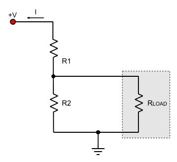
    When you have some time, could you shortly explain me what's the benefit of using 2N7000? I was thinking to use a simple voltage divider. Would that work? Is it a good practise?

    Thanks a lot,

    Monica

  • Monica, 

    The resistor divider is a cheap and easy solution and it likely works well for your application. However it has several drawback. First of all, it is not stable. If the current drawn from RLOAD changes, the voltage across RLOAD will also change. Another drawback is the current limitation. There are usually not resistors with the values required to achieve exactly the desired voltage drop (src http://pcbheaven.com/wikipages/The_Voltage_Divider/)

    I think you will find this document very handy (you will find the answer you are looking for at page 25). It helped me a lot. 

    Regards,

  • Hola Juan,

    Thank you very much! I will for sure read that.

    I thought it could only be something related with the current. Now it's much clearer. Thanks again!

    Best regards,

    Monica

    ps: We've tested today the optical link in the field and it works perfect. Thanks for sharing your experience! I didn't have to go through all the trials with coaxial cable and so on. 

  • You're welcome, Monica. Do not hesitate to contact me again if you have additional doubts.

    Regards, Juan.