This thread has been locked.

If you have a related question, please click the "Ask a related question" button in the top right corner. The newly created question will be automatically linked to this question.

F28027F LaunchPad - Debugger/GPAPUD

Other Parts Discussed in Thread: CONTROLSUITE

Hi all,

I bought the subject LaunchPad and proceeded to start the obligatory 'hello world' flashing LED project -which has been painful to say the least, but, after a few days I have figured out most of the ins & outs of CCS and the platform. 

My problem right now is that my code - toggle LEDs on button press - works fine when I step through it (F5) but if I actually play it  (F8 button) it seems to start running code  from flash (if that's possible)????EDIT: After it runs though once or possible a few times, not sure what it's clocked at. I am not certain about this but it looks like the temp/adc example that came loaded on it (no serial comms though)- LEDs 3 and 4 remain on and if I try to do anything in the debugger - eg pause, it crashes and gives me this error: No source available for "0x3f63b6" .... The code should just sit in an infinite loop, but it is getting out somehow?

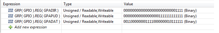
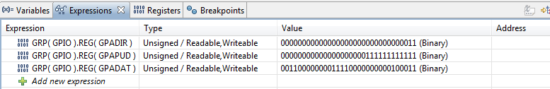
I'm also curious about the GPAPUD register - Pull up Disable Register - which I only set after manually playing in the registers and seeing that the push button latched without this set high? What does this actually do?

And how to use the "reset" tactile button as a GPIO switch? The schematic looks like I can put a jumper at J6-5 to J2-5 and use it as GPIO4. I would need to disable the reset on the mcu though (?)- and it also seems to lack a pull down resistor - so not sure if its even possible???

Finally, Can someone point me in the direction of a tutorial or something similar showing how to run a CCS project from flash? - cant seem to figure it out.

Thanks for help on any of the above.

code - meant to be as simple as possible - first time writing for ti gear/ full extent of my training is opening up the datasheet to the registers page- so any and all advice welcome. 

/*
* main.c
*/

#include "DSP28x_Project.h"
//#include "PeripheralHeaderIncludes.h"

//#pragma CODE_SECTION(InitFlash, "ramfuncs");
//#define Device_cal (void (*)(void))0x3D7C80

unsigned int i =0;
void main(void) {

EALLOW;
GpioCtrlRegs.GPAMUX1.bit.GPIO0 = 0; //Set to GPIO
GpioCtrlRegs.GPAMUX1.bit.GPIO0 = 0;

GpioCtrlRegs.GPAPUD.bit.GPIO12 =1; //Pull Up Disable Register

GpioCtrlRegs.GPADIR.bit.GPIO0 = 1;
GpioCtrlRegs.GPADIR.bit.GPIO1 = 1;
GpioCtrlRegs.GPADIR.bit.GPIO2 = 1; //Set GPIO 0-3 as Output
GpioCtrlRegs.GPADIR.bit.GPIO3 = 1;

GpioCtrlRegs.GPADIR.bit.GPIO12 = 0;
//GpioDataRegs.GPACLEAR.bit.GPIO0 = 1; // SET INPUT TO LOW.
//GpioDataRegs.GPACLEAR.bit.GPIO1 = 1;
//GpioDataRegs.GPACLEAR.bit.GPIO2 = 1;
//GpioDataRegs.GPACLEAR.bit.GPIO3 = 1;

EDIS;
GpioDataRegs.GPATOGGLE.bit.GPIO0 = 1;
GpioDataRegs.GPATOGGLE.bit.GPIO1 = 1;
GpioDataRegs.GPATOGGLE.bit.GPIO2 = 1;
GpioDataRegs.GPATOGGLE.bit.GPIO3 = 1;

while(1==1){
if(GpioDataRegs.GPADAT.bit.GPIO12 != 1)
{ GpioDataRegs.GPATOGGLE.bit.GPIO0 = 1;
GpioDataRegs.GPATOGGLE.bit.GPIO1 = 1;
GpioDataRegs.GPATOGGLE.bit.GPIO2 = 1;
GpioDataRegs.GPATOGGLE.bit.GPIO3 = 1;}
}


}

  • Sorry to hear you're having trouble.  Let's see if we can get you up and running.

    Execution shouldn't randomly jump between RAM and flash.  By default after loading a program CCS should put the PC at the start of main and every time you click restart it should bring you back there.  If that address changes as you suggest it does something really weird is going on...I highly doubt this is the case.  Could you tell me the exact name of the example you are trying to test with?

    Sometimes the LEDs on the board will light up for no apparent reason.  This is actually intention and meant to teach users about floating gates.  When the board powers up all of the IOs are Hi-Z and so are the inputs to the buffers which drive the LEDs.  These nets are effectively floating which makes it easy for charge to build up or dissipate.  This is what causes the LEDs to behave strangely if they are not actively driven.

    The push button on GPIO12 shouldn't latch and you shouldn't need to mess with the pull up.  Could you give a little more information on what you are experience in this regard.

    The reset push button isn't meant to be used for GPIOs.  While you could make it work, it would be painful and would require cutting traces.  I'd recommend you leave this alone and add your own push button if needed.

    There is an app note which describes how to make an application run from flash:

    http://www.ti.com/lit/pdf/spra958

    The Piccolo Multi-Day Workshop (online for free) also covers this topic as well as a lot of other good information about C2000 Devices:

    http://processors.wiki.ti.com/index.php/C2000_Piccolo_Multi-Day_Workshop

  • Thanks Trey, 

    *This isn't an example, although I have successfully run some control suite examples as well a 'blinker' example that was linked somewhere in the c2000 wiki - can't find it anymore -it's not a hardware issue at least. It's entirely possible I have some of the setup incorrect - couldn't find any succinct project setup document so I traced through examples to find the headers/etc required. Should have spent some time finding the documentation but what I have is the driverlib.lib, F2802x_Headers_nonBIOS.cmd and added the headers included in controlSUITE to the includes property so that DSP28x_Project.h could build.

    *Placing a break point at the end of the main loop, I can see that the registers are manipulated exactly as I wanted them.

    if I then let it go past the breakpoint (by turning it off, I can run it through to the breakpoint forever without issue) - where it should just sit in the loop, the registers spontaneously reset themselves to the following. (bit 12 of PUD went low-hard to see)

    This is where I thought it might be somehow running from flash but looking at the registers in real time, it seems that it's doing a whole lot of nothing at all, except for initially manipulating the registers once and then they are stable. -Need to figure out why it sets the registers to something without being told to. -Seems that the LEDS aren't lighting up as a result of IO hi-Z because the bits in GPADIR are set low for them?

    *Re GPIO12, I had a look at what was happening with a dmm and found that it wasn't latching per se but with out bit 12 of GPAPUD set high, the 'low' side of the switch floats at about 1.3V which I suppose is well above what the MCU thinks is low? - With  GpioCtrlRegs.GPAPUD.bit.GPIO12 =1 it goes to ground... Guess this is a consequence of the IOs being set up as high impedance. - Don't think this actually an issue, just something I hadn't come across before.

    Thanks. - I'll go ahead and try to run it out of flash and see if it still behaving strangely.

    Export of project attached.

    http://e2e.ti.com/cfs-file.ashx/__key/communityserver-discussions-components-files/171/3782.plAY.7z

  • Damn dog~

    -Forgot to handle the watchdog, SysCtrlRegs.WDCR= 0x0068; solves the problem. Actually had a bit of trouble finding the correct register value to disable (and later clear) the watchdog. Does TI have a document (F28027F) showing the bit makeup of each register (I assume they must but I can't find it in the datasheet or other suggested reading) - as in a row the width of the register with each bit named and then a table below with an explanation? 

    Thanks. - Time to try denouncing.

  • Patrick,

    Yes, but the marketing guys try their best to hide them :-P

    If you scroll down to the bottom half of the device page you'll see a section called User Guide:

    http://www.ti.com/product/tms320f28027#doctype6

    There should be a guide for each peripheral, and at the end of each guide you will find the register and bit descriptions.

    BR,