This thread has been locked.

If you have a related question, please click the "Ask a related question" button in the top right corner. The newly created question will be automatically linked to this question.

Maximum Transfer rate over serial connection for TMS320F28335

Other Parts Discussed in Thread: TMS320F28335, CONTROLSUITE

Hi,

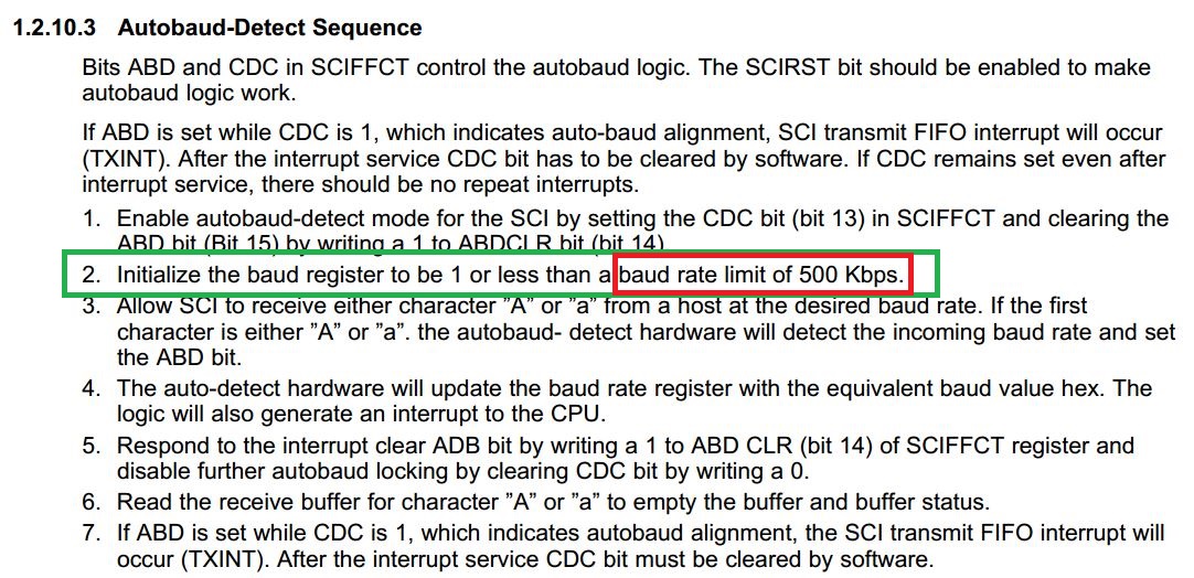
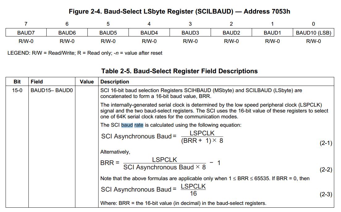
I'm using the eZDSP TMS320F28335  board by Spectrum digital. I want to use the ADC to sample 10KSPS and to send the resulting bits over a serial interface. This will require at least a 160kbps baud rate.

In the prototype stage, I want to use the GUI feature in code composer studio to display the readout data, and in more advanced stages, to extract it for real time processing in Matlab.

Does anybody know of any bottle neck on the side of the board or controller that would make this data rate of 160ksps in real time unattainable?

Thanks for reading

  • Hi,

    Here's extract in F28335_SCI documentation:

    Else, you can substitute the values in this formula and calculate the maximum achievable baud rate:

    Regards,

    Gautam

  • Thanks for your help Gautham, this clarifies a lot. Is there a suggested connection modality to attain this speed? I know the board I am using from spectrum digital has an SCI port with a VGA connection. Are you aware of any possibility of that causing us issues?

    Thanks again,


    Tim

  • I know the board I am using from spectrum digital has an SCI port with a VGA connection. Are you aware of any possibility of that causing us issues?

    VGA Connection ??? I guess you're talking about RS-232 connector! Here's how it might look like:

     or

    Actually SCI is not meant to handle such high speeds, also SCI connected directly on board without these connectors should be preferred. At very high speeds, data loss is expected but commenting further would be unfair better try and let me know :)

    Good luck & Regards,

    Gautam

  • The limit of 500kbps aplies only in autobaud sequence. The SCI baudrate limit is LSPCLK/16. In our product (with F28335 chip) we use 921.6kbps with no problem (without any cables - internal communication only).

    Regards, Andy

  • Thank you Andy, for sharing your experience.

    Regards,

    Gautam

  • Gautam,

    Yes, I meant RS232. I will try both SCI and CAN interfaces (because I am given nice RS232 connections for both) and let you know how each of them goes.

    As somebody who thinks in predominantly analog terms, and I admit we are going somewhat off topic, why is it that the bandwidth over bared wire connected directly to the board is better than that through a connection? Can you cite a source from where you got this interesting insight?

    Thanks,

    Tim

  • Hi Tim,

    why is it that the bandwidth over bared wire connected directly to the board is better than that through a connection? Can you cite a source from where you got this interesting insight?

    I've experienced the same while experimenting high data rates with SCI long time back. Also here's an article that you would like to read: http://digital.ni.com/public.nsf/allkb/2CABB3FD5CAF2F8686256F1D005AD0CD

    It says RS-232 can handle maximum of 160kbps data rate, but let me clarify that achieving high data rates depends on the quality of the connector. So refer RS-232 connectors datasheet, for the maximum speed it has been tested with.

    Also, I didn't know the fact that you're planning to connect 2 different boards via RS-232, just got to know that. Connecting 2 boards, off course RS-232 connectors seems to be a sound option and not bare wires!

    Tim, I didn't even mention the term bare wires before :)

    This is what I said:

    Gautam Iyer said:
    also SCI connected directly on board without these connectors should be preferred.

    Which meant, PCB tracks joining RX TX lines (As I thought that the serial interface was on the board itself)

    Regards,

    Gautam

  • Gautam, thanks for clarifying. I see you've troubleshot your own code at the end of the post before I could point out to you how I misinterpreted you.

    Tim

  • I am using the SCI loopback example provided in controlsuite, whose lower baud bits are set to 0x000F and higher bits are set to zero.

    As I understand, this results in a division of the LSPCLK (nominally 37.5MHz in the F28335) by 15, giving a baud rate of 2.5MBaud. When I set this to be the baud rate of the serial terminal application, I do not receive the correct values defined in hardware. It appears that the transmitter on the board and receiver in the PC are out of sync. Can anyone suggest to me why this is?

    Thanks,

    Tim

  • Tim, first of all I would like you to measure the exact baud rate on DSO too. Once you're sure what the baud rate is, use the same on the PC.

    Regards,

    Gautam

  • I did this, and got a baud rate of 294kbaud, which is plenty for my application. This means that the LSPCLK is 4.41MHz. I tried looking for this in the datasheet of the TMS320, but could not find much information. Can anyone suggest where in the project I should look to find how the central 150 MHz clock gets divided down to this value?

    Thanks for your advice, Gautam.

    Tim

  • Can anyone suggest where in the project I should look to find how the central 150 MHz clock gets divided down to this value?

    Here's where you can find the actual 150MHz getting divided, refer these 2 files in the project:

    i.) DSP2833x_SysCtrl.c

    ii.) DSP2833x_Examples.h

    Here's a screenshot too:

    Regards,

    Gautam