This thread has been locked.

If you have a related question, please click the "Ask a related question" button in the top right corner. The newly created question will be automatically linked to this question.

F28027 ADC 0v offset

Hi Folks

Have a Launchpad XL F28027. A using the ADC singa channel macro from the DPLib. The ADC result value does not seem to report correctly the values between 0 & 0.3v.

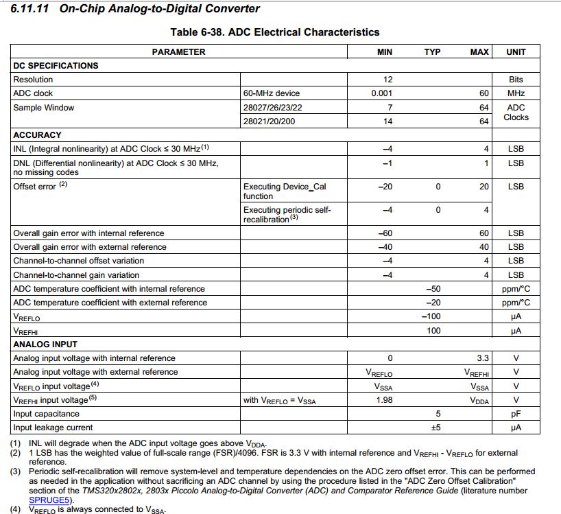
This is using the internal bandgap. DeviceCal() function has been called in devInit and the ADCREFTRIM register has been seen to be populated in the expressions window.

Is there anything we can try to reduce this issue?

Thanks

  • Hi Toby,

    The ADC result value does not seem to report correctly the values between 0 & 0.3v.

    Are the values varying a lot by the mean value or are you getting totally erroneous values?

    Regards,

    Gautam

  • Hi Gautam,

    We are seeing an ADC result of 0 for values between  0 - 0.03v, above which the ADCs appear to operate as expected, i.e. 0.07v produces the expected equivalent ADC result value as if the ADC's were working correctly.

    Thanks

  • Toby, are you using full range digital values? or are you using ">>x" expression while fetching AdcResults?

  • My mistake, the result values from the ADC appear to start at 0 at around > 0.03v

    so the 0.07v ADC result will be out by -0.03v. e.g. at about 0.04v we see ~4 - 7 in the ADC result register.

    I was using the Digital Power Lib ADC single channel macro to read the values from the ADCRESULT register, but now I am observing the register directly in the expressions window and still seeing the same issue.

    Thanks

  • I've noticed that this issue is not present with all the ADC's... ADCIN A0, A1 & A2 appear to function as expected, but the rest of the ADC's follow the issue as described above :\

  • Yup, there seems to be an offset as you've mentioned earlier. Do you feel ADCREFTRIM register is playing a part in this? Did you try commenting the same and just calling ADC calibration?

    Regards,

    Gautam

  • Gautam, 

    I will check this out - what is the way to call ADC_Cal()? to date I have used DeviceCal() as presented in the TI-made DevInit_F2802c.x file, as follows:

    #pragma CODE_SECTION(InitFlash, "ramfuncs");
    #define Device_cal (void   (*)(void))0x3D7C80
    
    void DeviceInit(void)
    {
    	//...
    	EALLOW;
    	SysCtrlRegs.PCLKCR0.bit.ADCENCLK = 1; // Enable ADC peripheral clock
    	(*Device_cal)(); // Auto-calibrate from TI OTP
    	// ...
    }
    
    void main (void) {
    	DeviceInit();
    	//...
    }

    A little more info on my setup: I have 13 of the ADCs in use, all SOCs triggered from EPWM1 SOCA with an acquisition window size of 7 samples, and each result read via the digital power library single channel ADC macro onto a 32-bit unsigned int "net" variable. I have tried this with two different LanchPad XL PCBs now

  • Gautam

    It is very odd that some of the ADCs (A0,A1,A2) work correctly and the rest dont... this would indicate that the calibration values are not to fault, would it not?

    As to change the values to suit the non-working ADCs would surely mean that the currently working ADCs would then no longer work correctly...

    EDIT: I just loaded up the Example_2802xAdcSoc example project and changed the channel selection to the one that is not A0,A1 or A2 and ran it, to find that the ADC (B4 in this case) works fine! Obviously this example project is quite a bit different from what I have running in my actual project in that it is exceedingly basic... however some things remain the same, such as the ADC basic initialisation, calibration. Th major difference being that I use stop-start mode rather than continuous mode, and that I use a lot more of the ADCs at the same time.

    Another difference is the trigger frequency. In the example project it is very slow in comparison, just 915 Hz. In my project I use a trigger at 43.3 kHz... though changing the example project to use the same period does not seem to impact its performance.

  • Hi Toby,

    It is very odd that some of the ADCs (A0,A1,A2) work correctly and the rest dont... this would indicate that the calibration values are not to fault, would it not?


    That's true and very odd... There should be nothing more than configuration issue.

    As to change the values to suit the non-working ADCs would surely mean that the currently working ADCs would then no longer work correctly.

    Did you try commenting the ADCREFTRIM register? If yes, what were your observations?

    Regards,

    Gautam

  • Gautam,

    I ran the example project again, which calls the InitSysCtrl() function from the file DSP2802x_SysCtrl.c. Within this file I commented out the call to DeviceCal(), replacing it with a call to AdcOffsetSelfCal() from the file DSP2802x_Adc.c, which sets OFFTRIM only, not REFTRIM. This didnt seem to result in any change.

    I proceeded by commenting out the the ADC cal altogether, which only resulted in the observed offset worsening to ~0.062v.

    Rgds

  • Toby, try these steps:

    1. Call InitAdc();

    2. Then call AdcOffsetSelfCal();

    These routines you would be able to find in "F2802x_Adc.c"

    Also, check these links out:

    http://e2e.ti.com/support/microcontrollers/c2000/f/171/t/232056.aspx

    http://e2e.ti.com/support/microcontrollers/c2000/f/171/t/72784.aspx

    FYI, here's ADC accuracy data:

    Regards,

    Gautam

  • Gautam,

    I realised that because the InitSys() (and DeviceCal()) is called before InitAdc(), in both the example and my project, the ADC is being power cycled and reset after it is calibrated.

    Thus, after your suggestion on the order toe call AdcOffsetSelfCall(), the issue is, somewhat, resolved.

    The previous ADC offset value being provided after DeviceCal() was 8. Using the AdcOffsetSelfCal this becomes 47.

    This means that the ADC result registers to record values other than zero within the 0v-0.03v range. However, to be precise the offset is now a little high! With some experimentation it seems like an offset value ~20 would be better suited. Also of note is that the offset disparity between the ADC results mentioned previously, still remains with these channels (A0, A1, A2) now reading slightly higher than the rest.... 

    This will however suffice for our purposes at this time.

    Thanks

  • That's great, Toby!

    Good luck and Regards,

    Gautam