Other Parts Discussed in Thread: CONTROLSUITE
According to the datasheet, TMX320F28377D PTP package has the GPIO99 port.
Does it exist?
Isn't there a mistake in the datasheet?

This thread has been locked.
If you have a related question, please click the "Ask a related question" button in the top right corner. The newly created question will be automatically linked to this question.
Other Parts Discussed in Thread: CONTROLSUITE
According to the datasheet, TMX320F28377D PTP package has the GPIO99 port.
Does it exist?
Isn't there a mistake in the datasheet?
Hi,
Yes, I already know that.
However, GPIO99 is not working.
So, I asked the question here.
I set the GPIO99 to the general-purpose output and change data register.
But, the port output is not changed.
I wonder that functionality of GPIO99 is vaild in TMX320F28377D PTP package.
GPIO99 is initialized in different way, unlike other pins?
I set the GPIO99 to the general-purpose output and change data register.But, the port output is not changed.
I hope you're using EALLOW and EDIS during configuration.
Also, check the example code present in controlSuite: gpio_toggle
Configure you're GPIO99 ie present in Group D of GPIO.
Let me know what you observe.
Regards,
Gautam
Thanks,
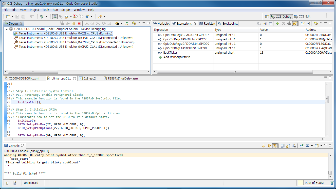
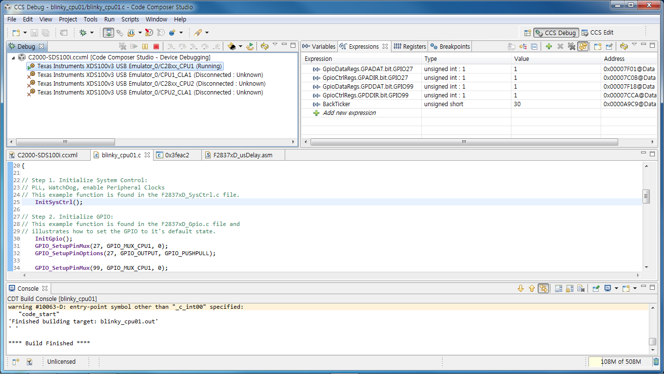
I use TI's basic example. (See attatched source file and capture image)
GPIO27 is work well(pin's logic state changed). But, GPIO99 is not work.
//###########################################################################
// FILE: blinky_cpu01.c
// TITLE: LED Blink Example for F2837xD.
//
//! \addtogroup cpu01_example_list
//! <h1> Blinky </h1>
//!
//! This example blinks LED X
//
//###########################################################################
// $TI Release: F2837xD Support Library v100 $
// $Release Date: Mon Dec 9 12:58:09 CST 2013 $
//###########################################################################
#include "F28x_Project.h" // Device Headerfile and Examples Include File
Uint16 BackTicker;
void main(void)
{
// Step 1. Initialize System Control:
// PLL, WatchDog, enable Peripheral Clocks
// This example function is found in the F2837xD_SysCtrl.c file.
InitSysCtrl();
// Step 2. Initialize GPIO:
// This example function is found in the F2837xD_Gpio.c file and
// illustrates how to set the GPIO to it's default state.
InitGpio();
GPIO_SetupPinMux(27, GPIO_MUX_CPU1, 0);
GPIO_SetupPinOptions(27, GPIO_OUTPUT, GPIO_PUSHPULL);
GPIO_SetupPinMux(99, GPIO_MUX_CPU1, 0);
GPIO_SetupPinOptions(99, GPIO_OUTPUT, GPIO_PUSHPULL);
// Step 3. Clear all interrupts and initialize PIE vector table:
// Disable CPU interrupts
DINT;
// Initialize the PIE control registers to their default state.
// The default state is all PIE interrupts disabled and flags
// are cleared.
// This function is found in the F2837xD_PieCtrl.c file.
InitPieCtrl();
// Disable CPU interrupts and clear all CPU interrupt flags:
IER = 0x0000;
IFR = 0x0000;
// Initialize the PIE vector table with pointers to the shell Interrupt
// Service Routines (ISR).
// This will populate the entire table, even if the interrupt
// is not used in this example. This is useful for debug purposes.
// The shell ISR routines are found in F2837xD_DefaultIsr.c.
// This function is found in F2837xD_PieVect.c.
InitPieVectTable();
BackTicker = 0;
// Enable global Interrupts and higher priority real-time debug events:
EINT; // Enable Global interrupt INTM
ERTM; // Enable Global realtime interrupt DBGM
// Step 6. IDLE loop. Just sit and loop forever (optional):
for(;;)
{
BackTicker++;
//
// Turn on LED
//
GPIO_WritePin(27, 0);
GPIO_WritePin(99, 0);
//
// Delay for a bit.
//
DELAY_US(1000*500);
//
// Turn off LED
//
GPIO_WritePin(27, 1);
GPIO_WritePin(99, 1);
//
// Delay for a bit.
//
DELAY_US(1000*500);
}
}
Hi,
Try using this:
EALLOW;
GpioCtrlRegs.GPDMUX1.bit.GPIO99 = 0;
GpioCtrlRegs.GPDDIR.bit.GPIO99 = 1; // GPIO99 = output
EDIS;
GpioDataRegs.GPDSET.bit.GPIO99 = 1; //Set GPIO99
Regards,
Gautam
Hi Nam,
Which revision of F28377D silicon do you have? On Rev. 0 material, that pin was a TI internal test pin, whereas on Rev. A it should now be GPIO99.
Hi,
I have tested with chip of silicon revision 0.
My question is solved, thanks to you.
Thank you, Devin for the clarification. Do you have a document which has the changes/modifications in Rev.A wrt Rev.0 in other words a revision record sheet?
Regards,
Gautam
Gautam,
Changes like this would normally be listed in the errata. I will investigate why it is not...