This thread has been locked.

If you have a related question, please click the "Ask a related question" button in the top right corner. The newly created question will be automatically linked to this question.

F28M36 blinky odd behaviour

Other Parts Discussed in Thread: CONTROLSUITE, F28M36P63C2

Hello,

I'm trying to use the blinky example as a base from which to develop my own implementation.

I have imported the projects from controlSUITE, under F28M36x / Code examples / Dual System Example Projects / blinky (v201)

Compiling and loading the example program for the respective cores seems to work correctly: the LEDs on the board to blink as one would expect.

However, changing the example code in the M3 side results in odd behaviour. Compilation process seems as if everything is in order, that is I get no compilation errors when building the project. Loading the program works, but when running the program nothing happens: LED stops working, nothing in the program seems to happen.

Changing the example code, adding code or even commenting out seemingly irrelevant lines results in everything going astray.

For example even commenting this out (LED0 peripheral not used in M3) breaks functionality:

//SysCtlPeripheralEnable(LED_0_PERIPH);

Suspending execution with the edited program results in the following:

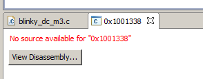
When using the unedited example source suspending the execution results in CCS showing the line where execution has stopped as expected.

Once a "broken" program is reverted back to be equivalent to the example code, rebuilt and re-loaded everything works again so it feels to me this has something to do with the innards of the object file being loaded. However I do not have any idea where to even start looking.

HW/SW specs:

F28M36P63C2 + Docking station

CCS version: 5.5.0.00077

Thanks in advance for any replies.

  • Hi,

    At start up (as soon as you power up the controlCard), the M3 owns all the GPIOs. In Order to run any of the C28 example codes, you first need to import the setup_m3 project , build and load it to the M3. Once you do that import the blinky project build it and load it to the C28. Once the executable files are loaded, run the M3 first and then run the C28.

    Regards,

    Gautam

  • Thank you for your reply.

    I have gotten the blinky example project for C28 and M3 to work perfectly fine. Both LEDs blink and all is well.

    My problem is that once you change the source for the M3 in some way, all functionality seems to break. Also somehow the debugger neither has a clue what's going on when the program is suspended as I explained in the original post.

  • My problem is that once you change the source for the M3 in some way, all functionality seems to break. Also somehow the debugger neither has a clue what's going on when the program is suspended as I explained in the original post.

    I would like one of my TI buddy to help you out. Be patient :)

    Regards,

    Gautam

  • Thanks Gautam, appreciate your help and insight.

    Vile,

    it depends on what you are editing. For ex: if you comment out any of the sysctrlPreipheralEnable then you cannot write to any of the peripheral registers and the writes would result in an exception.

    Now if your application has NVIC BASE moved to flash or RAM and the application is installing needed ISRs to catch the exceptions then program control branches to the application installed ISR routines if not the default exception handlers from boot ROM would be fetched. The location 0x01001338 belongs to boot ROM and since there is no source code CCS will point to dis-assembly.

    Bottom line is what you are changing in the source would explain the resulting behavior, please refer to the driverlib sources in ControlSuite and the device TRM for more details.

    Best Regards

    Santosh