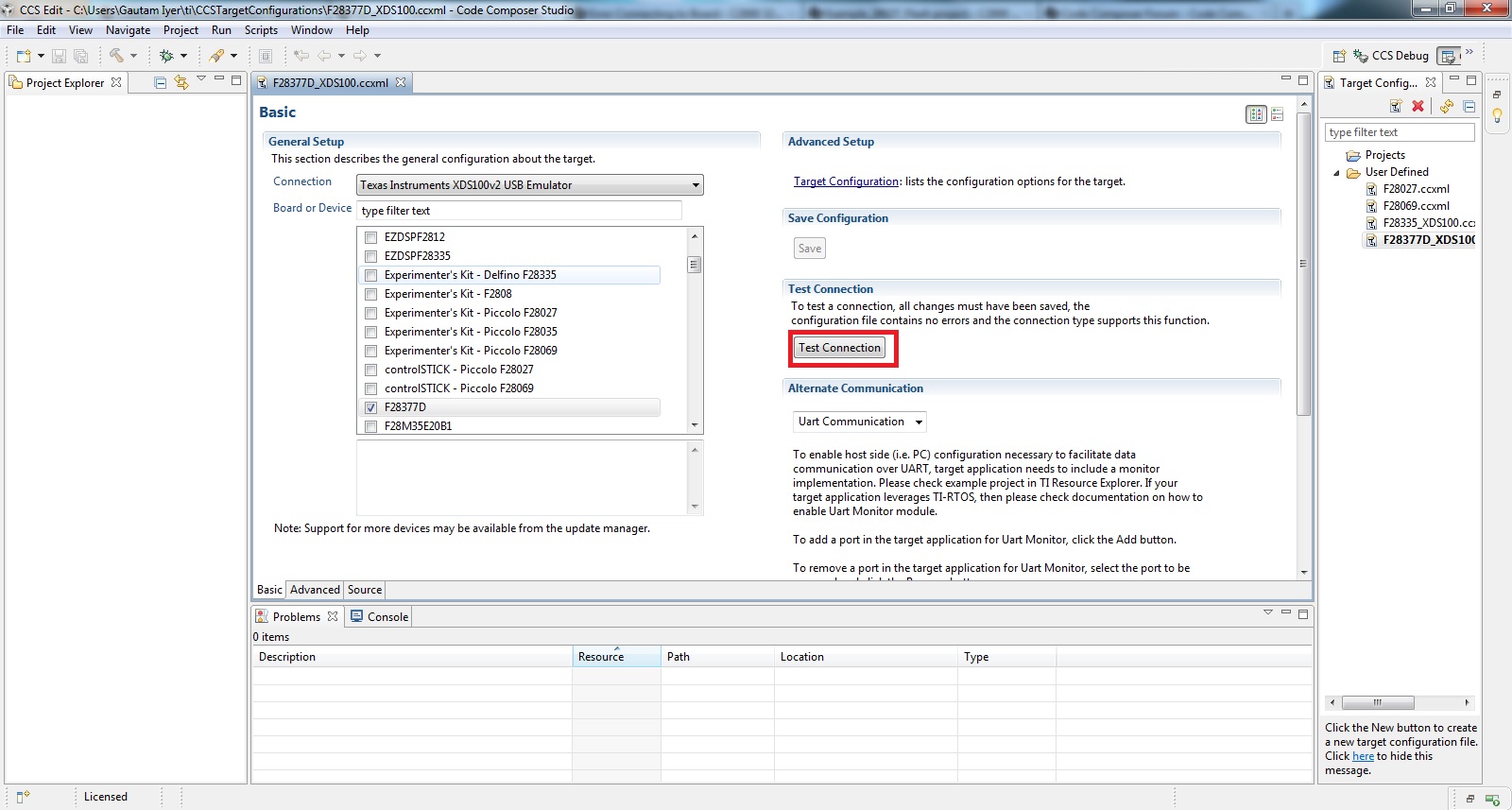
I am trying to program F28035 Piccolo Control Card using a Experimnerter's Kit USB docking station. But I keep getting the following error message while trying to debug the code:

I am using CCS version 5.3 on Windows 64bit system!
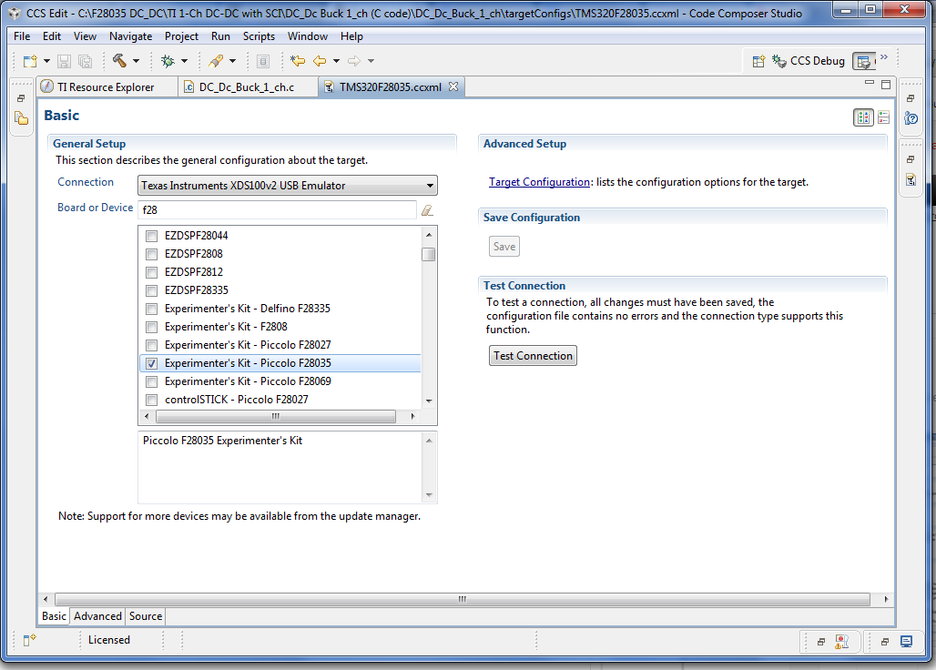
I am trying to program F28035 Piccolo Control Card using a Experimnerter's Kit USB docking station. But I keep getting the following error message while trying to debug the code:
I am using CCS version 5.3 on Windows 64bit system!