This thread has been locked.

If you have a related question, please click the "Ask a related question" button in the top right corner. The newly created question will be automatically linked to this question.

TMS320F28335 - Experimental Kit - Lower V and Lower I issues

Other Parts Discussed in Thread: TMS320F28335, CONTROLSUITE

Hi,   I am using TI's Experimental Kit TMS320F28335 MCU for voltage and current measurements. I am having trouble getting accurate reading on a day-today basis for lower voltage and current range. My code works fine for higher voltage.

 Do you have a circuit module compatible with F28335, that gives accurate reading for measuring voltage and current values at lower ranges?

Regards     ATul Bhakay

  • Hi Atul,

     Do you have a circuit module compatible with F28335, that gives accurate reading for measuring voltage and current values at lower ranges?

    First of all, is your curve linear wrt to actual values and ADCin values (before feeding it to ADC)? Please make a table of both these values and plot a curve esp. at lower values where you're facing issues. We would get an idea, where the issue is.

    Regards,

    Gautam

  • Dear Gautam,

    Mr. Atul posted my query before I could post it.

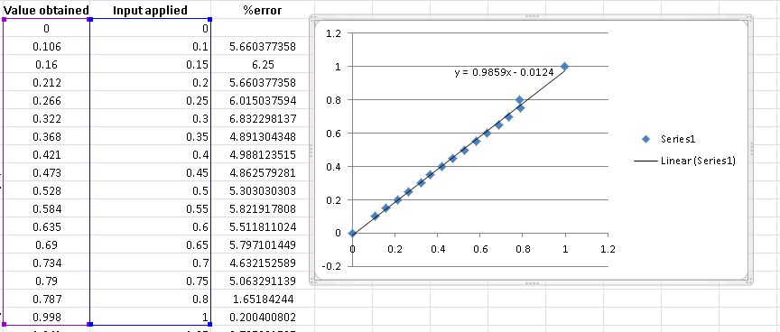
    Find attached graph and readings for low voltage measurements. If you only see the graph, it might look linear but when the percentage error is calculated, the large error is noticeable. For higher voltage the % error is well below 1%. The values were obtained after implementing the "Offset Error Correction" method in SPRU812A pg.31 in my code.

    The slope and the offset values were obtained using excel. These values were used for curve fitting to reduce the error in the next iteration of measurements  but the error is not constant through out the day. For couple of days after curve fitting I observed voltage values three times a day but still I observe variation in the error.

    I also used four constant reference voltage (GND,1.5, 2.5, 3V ), calculated the curve fitting values for slope and offset at every run time in my code but still I am getting errors.

    My main issue is that my measurements are not constant day-after-day for voltage and current.

    Best Regards,

    Pankaj

  • Thanks for the detailed table and graph. I would like to confirm that the:

    Value obtained column is before ADC input right? or is it the measured from ADCResult register?

    Also, if the Value Obtained column is before ADCin then what are the respective analog values you're getting on CCS Watch window?

    Here's the table which would give you close look:

    8816.Book1.xlsx

    Do fill in your values and share.

    Regards,

    Gautam

  • Dear Gautam,

    For testing the ADC, I made use of a divider with a variable resistor pot. I gave different DC input to the ADC pin and obtained the above graph.

    I saw your attached table,  In my setup the "Actual input" = "ADC Input" = "Input applied".

    The "Input applied" are the input to the ADC, measured through Tektronix scope. Analog input.

    The "value obtained" are from CSS watch window, I wrote a function in my code to convert the digital values to volts and then display them. 

    The values in the table you have provided are true in an ideal condition. In practical application the digital value keeps changing by few bits. I am able to compensate for that slight change but that change which I observe is not constant day-after day. As a result even after calibrating for the change today, the next day I still get error in the reading and have to re-calibrate again. 

    After calibration I am given the ADC pin an AC signal, I have plotted that signal and its clean (noise free). I have also played with sampling rate but no help. 

    Are there any filters or circuits I can use to improve accuracy of the ADC?

    Best Regards,

    Pankaj 

  • The values in the table you have provided are true in an ideal condition. In practical application the digital value keeps changing by few bits. I am able to compensate for that slight change but that change which I observe is not constant day-after day. As a result even after calibrating for the change today, the next day I still get error in the reading and have to re-calibrate again.

    Very true. Mine were just for an example. Yes, they do flicker a lot!

    The "value obtained" are from CSS watch window, I wrote a function in my code to convert the digital values to volts and then display them.

    Then the values obtained are good enough. Yes, I agree that they are not perfect but they very much match to the applied values.

    Are there any filters or circuits I can use to improve accuracy of the ADC?

    You can use input RC filters (hardware) or you can use filter implementations (software: available in controlSuite)

    I never used any "Offset Error Correction" method or configuring any offset registers as my ADCs were always true to the scale. But in all, your table looks quite satisfactory to me :)

    For higher effective values you can go for filters or averaging of 16/32/64 ADC values!

    Regards,

    Gautam

  • Dear Gautam,

    Thank you, for your reply and trying things out.

    "Offset Error Correction" is done by default by the Adc_Cal() during start-up and default values are loaded. To reduce the flicker, it has to be done in real-time. It does help but doesn't reduce all the error for my application. Then I used curve fitting which brings it lower but not below 1%. The error is high for lower voltages.

    I will try with filters, next. Which filters should I go for, low pass or high pass or some different type?  As my signal looks clean after plotting it from the CSS watch window.

    Is there a reason to average values in the multiple of 16 (32/64) as  the ADC is 12bit. Just wanted to know. 

    Best Regards,

    Pankaj

  • I will try with filters, next. Which filters should I go for, low pass or high pass or some different type?  As my signal looks clean after plotting it from the CSS watch window.

    LPF would do the trick but do take care of the added delay due to its inclusion to your circuitry.

    Is there a reason to average values in the multiple of 16 (32/64) as  the ADC is 12bit. Just wanted to know.

    Its just a figure and might vary application wise (any multiple of 2 should be preferred).

    Regards,

    Gautam