This thread has been locked.

If you have a related question, please click the "Ask a related question" button in the top right corner. The newly created question will be automatically linked to this question.

Trouble IDing motor using DRV8301 BoosterPack +F2807F

Other Parts Discussed in Thread: MOTORWARE, TMS320F28377D

Hi,

I am trying to ID my motor using this kit and running Proj 2c. I most likely do not have the correct parameters set for the motor due to my lack of understanding of what the variables are. I have attached the relevant parameters in the user.h file.

If I need to run the ID at slow speed (<100°/s), is USER_IQ_FULL_SCALE_FREQ_Hz the correct variable to change?

Thanks!8055.5165.User.h

  • Please read the attached and place here, it was not included in the last revision of MotorWare

    C:\ti\motorware\motorware_1_01_00_11\docs\guis\universal\

    Use the spreadsheet from here to set-up your user.h

    http://e2e.ti.com/support/microcontrollers/c2000/f/902/t/319433.aspx

    What do you mean you need to ID at slow speed?  You need to ID at a speed up to ~10% of the maximum speed. This is controlled through

    USER_MOTOR_FLUX_EST_FREQ_Hz

    You have this set at 0.2 Hz!  Unacceptable.

    You also have a Flux of 58 V/Hz set. I'm not sure if you THINK this is correct, but there is almost no way it is....if it is true you are using a very, very high voltage motor and shouldn't be using a 24V/10A inverter. 

    Please tell me about your motor:
    Vbus
    Poles (if known)
    Maximum Current at Load
    Maximum Speed


    qsg_gui_universal.pdf
  • Hi Chris,

    Thank you for getting back to me. 

    You are correct this is a large motor, and this kit is definitely not ideal. Won't get into all the rationale behind that, suffice to say I purchased it out of my own pocket to save time and hassle, and wanted to do a sanity check. There is a TI HV kit that was purchased a couple of years ago, but does not have all the latest technology.

    I have found your spreadsheet just prior to your response and am looking through it now. Am I correct that USER_MOTOR_RATED_FLUX and USER_MOTOR_Ls_d is what will be ID'd during the ID process?

    VBus is just < 400V

    24 Poles

    Max speed = 6 rpm

    Max current @ load = 10A

  • The maximum speed of the motor is 6 RPM = 1.2 Hz?

    What is the purpose of a motor like this?

    You won't be succesful with a Bemf based observer like FAST at 1.2 Hz maximum speed.  If this is not an error I suggest you use an encoder, halls, or a saliency/saturation technique for rotor flux angle estimation.


  • Hi Chris,

    If I run at 10 rpm, is the kit capable of doing this? What is the minimum velocity for the FAST?

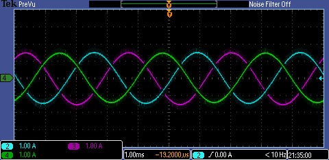
    I updated the values according to the spreadsheet, but it seems the ID code runs at the same velocity. I haven't had a chance to go through the entire code sample yet, but can I set the velocity at a lower speed, such as 60 - 100°/s? I changed the Maximum RPM motor will run cell in spreadsheet to 10 RPM, and I'm seeing the same result on the scope after plugging in the calculated numbers (see attached file). I would like to drive the motor at a much lower speed.

  • Tim,

    I think your expectations of the InstaSPIN-FOC solution are not correct.  InstaSPIN-FOC is a sensorless solution which uses an algorithm called FAST for estimation of the rotor flux angle based only on currents and voltages.  With proper rotor flux angle knowledge a field oriented torque controller can be produced quite easily.

    FAST is dependend on the phase voltage measurements and the Bemf of the motor. The lowest speeds which it can produce acceptable angle estimations is dependendent on the measurements of these phase voltages that only occur when the rotor has some movement.  HOW slow the rotor can go depends on the Bemf the rotor produces and how accurate / resolution you can measure.   In practice for most motors good operation can be had in the 2 Hz range with well scaled voltage sensing.  Some motors have very small flux and this opeation point moves to > 10 Hz.  Some have VERY large flux and can move < 0.1 Hz

    To run, FAST needs to know for a synchronous machine the Rs, Flux, and Ls.  You can enter these if known or use the motor identification procedure.  This procedure requires the motor to be run to 10% of the rated speed for Flux and Ls identification.  So you have to use a proper power supply and inverter to allow.

    I really don't understand the requirements of your motor though. I've never heard of a motor that ONLY goes to 10 RPM. The Bemf would be absolutely enormous. 

    Either way, IF your motor does have these charachteristics a sensorless motor model based approach for estimation (like FAST) is not for you.  I strongly recommend you use a mechanical rotor sensor like an encoder or resolver for rotor angle feedback to control your commutation.  InstaSPIN-MOTION may be able to help you in this regard.


  • Hi Chris,

    I understand that what I'm doing is somewhat unusual and also not using the right HW. At the moment I'm only trying to do a "sanity" check (although the test is in question and so is the sanity.)

    Can you help point me to:

    1. Where in the code can I limit the commanded velocity?

    2. Can I make this type of motor turn at all using this kit, for now?

    Thanks.

    ps. As an aside, one of my colleagues just pointed out to me that the new TMS320F28377D is not available as a selection in the latest CCS for New Project.

  • Tim,

    I would need accurate information about the motor before I said if you could get it running at all, much less the 24V/10A kit.

     I just don't believe this is only a 10 RPM motor.  If it is, there is no way you are running this sensorless with this kit that is scaled for 26V maximum.  If you really have 86 V/Hz flux you will saturate the Vph measurement at 0.25 Hz

    It just makes no sense.


    The new 28377D devices require CCSv5p5 and latest updates for support.
    http://e2e.ti.com/support/microcontrollers/c2000/f/171/t/310052.aspx