This thread has been locked.

If you have a related question, please click the "Ask a related question" button in the top right corner. The newly created question will be automatically linked to this question.

Error conneting to TMS320F28055 with CCS 5.5.0

Other Parts Discussed in Thread: TMS320F28055

I purchased  piccolo F28055 experimenter kit.

when click the debug button, I can see the below message and can not download code to target board.

Error connecting to the target:
(Error -1135 @ 0x0)
The emulator reported an error. Confirm emulator configuration and connections, reset the emulator, and retry the operation.
(Emulation package 5.1.232.0)

 CCS version is  5.5.0(free) and OS is windows 7(32bit) 

test connection

[Start]

Execute the command:

%ccs_base%/common/uscif/dbgjtag -f %boarddatafile% -rv -o -F inform,logfile=yes -S pathlength -S integrity

[Result]


-----[Print the board config pathname(s)]------------------------------------

C:\Users\HAKILHO\AppData\Local\.TI\693494126\
0\0\BrdDat\testBoard.dat

-----[Print the reset-command software log-file]-----------------------------

This utility has selected a 100- or 510-class product.
This utility will load the adapter 'jioserdesusb.dll'.
The library build date was 'Aug 20 2013'.
The library build time was '22:56:19'.
The library package version is '5.1.232.0'.
The library component version is '35.34.40.0'.
The controller does not use a programmable FPGA.
The controller has a version number of '4' (0x00000004).
The controller has an insertion length of '0' (0x00000000).
This utility will attempt to reset the controller.
This utility has successfully reset the controller.

-----[Print the reset-command hardware log-file]-----------------------------

The scan-path will be reset by toggling the JTAG TRST signal.
The controller is the FTDI FT2232 with USB interface.
The link from controller to target is direct (without cable).
The software is configured for FTDI FT2232 features.
The controller cannot monitor the value on the EMU[0] pin.
The controller cannot monitor the value on the EMU[1] pin.
The controller cannot control the timing on output pins.
The controller cannot control the timing on input pins.
The scan-path link-delay has been set to exactly '0' (0x0000).

-----[The log-file for the JTAG TCLK output generated from the PLL]----------

There is no hardware for programming the JTAG TCLK frequency.

-----[Measure the source and frequency of the final JTAG TCLKR input]--------

There is no hardware for measuring the JTAG TCLK frequency.

-----[Perform the standard path-length test on the JTAG IR and DR]-----------

This path-length test uses blocks of 512 32-bit words.

The test for the JTAG IR instruction path-length failed.
The JTAG IR instruction scan-path is stuck-at-ones.

The test for the JTAG DR bypass path-length failed.
The JTAG DR bypass scan-path is stuck-at-ones.

-----[Perform the Integrity scan-test on the JTAG IR]------------------------

This test will use blocks of 512 32-bit words.
This test will be applied just once.

Do a test using 0xFFFFFFFF.
Scan tests: 1, skipped: 0, failed: 0
Do a test using 0x00000000.
Test 2 Word 0: scanned out 0x00000000 and scanned in 0xFFFFFFFF.
Test 2 Word 1: scanned out 0x00000000 and scanned in 0xFFFFFFFF.
Test 2 Word 2: scanned out 0x00000000 and scanned in 0xFFFFFFFF.
Test 2 Word 3: scanned out 0x00000000 and scanned in 0xFFFFFFFF.
Test 2 Word 4: scanned out 0x00000000 and scanned in 0xFFFFFFFF.
Test 2 Word 5: scanned out 0x00000000 and scanned in 0xFFFFFFFF.
Test 2 Word 6: scanned out 0x00000000 and scanned in 0xFFFFFFFF.
Test 2 Word 7: scanned out 0x00000000 and scanned in 0xFFFFFFFF.
The details of the first 8 errors have been provided.
The utility will now report only the count of failed tests.
Scan tests: 2, skipped: 0, failed: 1
Do a test using 0xFE03E0E2.
Scan tests: 3, skipped: 0, failed: 2
Do a test using 0x01FC1F1D.
Scan tests: 4, skipped: 0, failed: 3
Do a test using 0x5533CCAA.
Scan tests: 5, skipped: 0, failed: 4
Do a test using 0xAACC3355.
Scan tests: 6, skipped: 0, failed: 5
Some of the values were corrupted - 83.3 percent.

The JTAG IR Integrity scan-test has failed.

-----[Perform the Integrity scan-test on the JTAG DR]------------------------

This test will use blocks of 512 32-bit words.
This test will be applied just once.

Do a test using 0xFFFFFFFF.
Scan tests: 1, skipped: 0, failed: 0
Do a test using 0x00000000.
Test 2 Word 0: scanned out 0x00000000 and scanned in 0xFFFFFFFF.
Test 2 Word 1: scanned out 0x00000000 and scanned in 0xFFFFFFFF.
Test 2 Word 2: scanned out 0x00000000 and scanned in 0xFFFFFFFF.
Test 2 Word 3: scanned out 0x00000000 and scanned in 0xFFFFFFFF.
Test 2 Word 4: scanned out 0x00000000 and scanned in 0xFFFFFFFF.
Test 2 Word 5: scanned out 0x00000000 and scanned in 0xFFFFFFFF.
Test 2 Word 6: scanned out 0x00000000 and scanned in 0xFFFFFFFF.
Test 2 Word 7: scanned out 0x00000000 and scanned in 0xFFFFFFFF.
The details of the first 8 errors have been provided.
The utility will now report only the count of failed tests.
Scan tests: 2, skipped: 0, failed: 1
Do a test using 0xFE03E0E2.
Scan tests: 3, skipped: 0, failed: 2
Do a test using 0x01FC1F1D.
Scan tests: 4, skipped: 0, failed: 3
Do a test using 0x5533CCAA.
Scan tests: 5, skipped: 0, failed: 4
Do a test using 0xAACC3355.
Scan tests: 6, skipped: 0, failed: 5
Some of the values were corrupted - 83.3 percent.

The JTAG DR Integrity scan-test has failed.

[End]

I have searched such problems, but I could not solve it. 

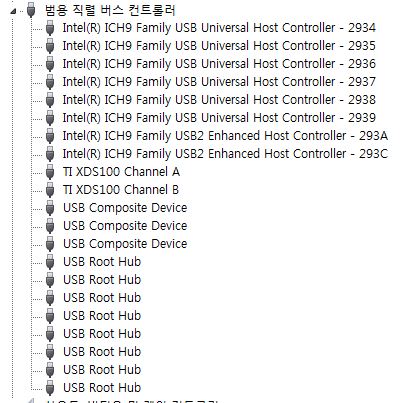
I think USB cable is working and windows driver is perfectly installed

and the LD1, LD3 on the board are turned on

I have check the Texas Instruments XDS100V1,2,3 USB Emulator.

all of usb emulator shows same error message.

;(

  • Hi,

    Did you check the same on another pc? Also, was this kit working before or this is for the first time?

    Regards,

    Gautam

  • Hello~ 

    I have not checked on another pc. just tested my pc. 

    this is first time to use the kit. 

    should I try it on another pc??

  • Yup, please try it on another PC. Do revert with your observations.

  • I have tried several times on another PC. but the same message and error ware shown on the screen.

    could you give me another advice?

  • Ok, are the drivers installed properly? Check your device manager.

    Also go through these links:

    http://processors.wiki.ti.com/index.php/XDS100#Troubleshooting_FAQ

    http://processors.wiki.ti.com/index.php/Debugging_JTAG_Connectivity_Problems

    Regards,

    Gautam

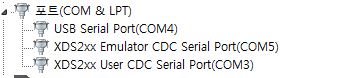
  • yes, Windows 7 installed the drivers automatically. and check my  device manager.

    there are not any warning.

    I have questions.

    as I mentioned, I bought the piccolo F28055 Experimenter Kit.

    and PC connected with docking station by USB cable.

    so, what  should I select the Texas Instruments XDS100v1 usb emulator(TMS320F28055) or (Experimenter's kit - piccolo F28055) in TMS320F28055.ccxml file?

    but there is no Experimenter's kit - piccolo TMS320F28055 in ccxml file.

    is it possible to use Experimenter's kit, by choosing TMS320F28055 in ccxml file?

  • so, what  should I select the Texas Instruments XDS100v1 usb emulator(TMS320F28055) or (Experimenter's kit - piccolo F28055) in TMS320F28055.ccxml file?

    but there is no Experimenter's kit - piccolo TMS320F28055 in ccxml file.

    is it possible to use Experimenter's kit, by choosing TMS320F28055 in ccxml file?

    Both should work. Also do check this out: http://e2e.ti.com/support/microcontrollers/c2000/f/171/t/304335.aspx

    In short please check the voltage levels on the board.

    Regards,

    Gautam

  • first of all I must say thank you, Gautam.

    I have checked the voltage level. 

    when probe the VDD, VDDIO, VDDA on TMS320F28055 MCU pin, those are 1.823, 3.283, 3.29. 

    the voltage level is appropriate.

    and TP1, TP2, TP3(5V, 3.3V, GND) are 5V, 3,29V

    in the case of JPEG part on controlCARD, TPA1, TPA2, TPA3(5V, 3,3V, GND) are 4.61V, 3.3V.

    and I also check the VCORE, VCCIO, VREGOUT(1.8V, 3.3V, 3.3V) of FTDI(FT2232HL) are 1.8V, 3.29V, 3.29V

    on the Docking-station. 5V, 3V are checked on TEST point. regulator is perfectly working.

    and than I check the VCC, VCCIOA, VCCIOB(4.35~5.25V, 3.0~5.25V) of FTDI(FT2232D) are 5.1V, 3.325V, 3.325V.

    most of voltage level is in operation condition.

    what is wrong with me....... I am CHAOS.

  • That's very strange! Do you've an external XDS100 emulator or any other experimenter's kit?

    Regards,

    Gautam

  • I have XDS 200 emulator and do not have another experimenter's kit.

    what is strange thing? could you explain it? please~~. 

  • Try using your XDS200; insert it in J2. That should work... Let me know what you observe. Select XDS200 in target configuration window.

    Regards,

    Gautam

  • when switch 4 position 1 on

    [Start]

    Execute the command:

    %ccs_base%/common/uscif/dbgjtag -f %boarddatafile% -rv -o -S integrity

    [Result]


    -----[Print the board config pathname(s)]------------------------------------

    C:\Users\HAKILHO\AppData\Local\.TI\693494126\
    0\0\BrdDat\testBoard.dat

    -----[Print the reset-command software log-file]-----------------------------

    This utility has selected a 560/2xx-class product.
    This utility will load the program 'xds2xxu.out'.
    The library build date was 'Aug 20 2013'.
    The library build time was '23:33:52'.
    The library package version is '5.1.232.0'.
    The library component version is '35.34.40.0'.
    The controller does not use a programmable FPGA.
    The controller has a version number of '12' (0x0000000c).
    The controller has an insertion length of '0' (0x00000000).
    This utility will attempt to reset the controller.
    This utility has successfully reset the controller.

    -----[Print the reset-command hardware log-file]-----------------------------

    This emulator does not create a reset log-file.

    -----[An error has occurred and this utility has aborted]--------------------

    This error is generated by TI's USCIF driver or utilities.

    The value is '-233' (0xffffff17).
    The title is 'SC_ERR_PATH_BROKEN'.

    The explanation is:
    The JTAG IR and DR scan-paths cannot circulate bits, they may be broken.
    An attempt to scan the JTAG scan-path has failed.
    The target's JTAG scan-path appears to be broken
    with a stuck-at-ones or stuck-at-zero fault.

    [End]

    when switch 4 position 1 off.

    [Start]

    Execute the command:

    %ccs_base%/common/uscif/dbgjtag -f %boarddatafile% -rv -o -S integrity

    [Result]


    -----[Print the board config pathname(s)]------------------------------------

    C:\Users\HAKILHO\AppData\Local\.TI\693494126\
    0\0\BrdDat\testBoard.dat

    -----[Print the reset-command software log-file]-----------------------------

    This utility has selected a 560/2xx-class product.
    This utility will load the program 'xds2xxu.out'.
    The library build date was 'Aug 20 2013'.
    The library build time was '23:33:52'.
    The library package version is '5.1.232.0'.
    The library component version is '35.34.40.0'.
    The controller does not use a programmable FPGA.
    The controller has a version number of '12' (0x0000000c).
    The controller has an insertion length of '0' (0x00000000).
    This utility will attempt to reset the controller.
    This utility has successfully reset the controller.

    -----[Print the reset-command hardware log-file]-----------------------------

    This emulator does not create a reset log-file.
    E_RPCENV_IO_ERROR(-6) No connection: DTC_IO_Send::dtc_io

    -----[An error has occurred and this utility has aborted]--------------------

    This error is generated by TI's USCIF driver or utilities.

    The value is '-233' (0xffffff17).
    The title is 'SC_ERR_PATH_BROKEN'.

    The explanation is:
    The JTAG IR and DR scan-paths cannot circulate bits, they may be broken.
    An attempt to scan the JTAG scan-path has failed.
    The target's JTAG scan-path appears to be broken
    with a stuck-at-ones or stuck-at-zero fault.

    [End]

    eventually 

    after test connection, XDS200 turn it off. 

  • Ha,

    Why do you have that long extender strap on the XDS200 cable?  Can't you plug the XDS200 directly in to the docking station connector?

    Also, try to power the docking station from the 5V connector, and not from the USB.

    I suspect at the end of the day, either the XDS100 chip on your ControlCard is damaged, or the F28055 on the ControlCard is damaged.  From what you showed in your previous posts, the 'Test Connection' had some partial fails (as opposed to complete failure).  That suggests a hardware problem.  You probably have to contact TI and exchange the development kit for a new one.

    - David

  • yep. I can not plug the XDS200 directly in to the docking station connector.

    because of PCB of converter. like this

    so I use extended cable.

    David, thank you for your advice and I will try to power from the 5V connector.

  • Ha,

    I see.  I forgot SD XDS200 uses small size connector, and you need to use the adaptor.  The extender cable you are using is very long.  That can make the XDS200 connection fail.  You want the extender cable to be as short as possible.

    The reason I mentioned the 5V plug is because I want to be certain the on-board XDS100 is out of the way.  It should be when you plug in an external emulator, but I want to be 100% certain.

    Getting the XDS200 to connect to the board just tells us that the C2000 itself is OK, and the problem is with the XDS100.  If the XDS200 cannot connect, that suggests the C2000 has the problem.  None of that really helps too much though, as at the end of the day there is still a problem with the hardware and you probably want to return it and get a replacement.  It is always good to run some tests I suppose.

    Regards,

    David

  • I tested with power 5V.

    finally, it failed to operate the target board(TMS320F28055 with docking station).


    when powered to target board, I check the test point to know voltage level. those are in normal condition.

    as you mentioned, C2000 has the problem. CCS showed the some error for me

    ;(