This thread has been locked.

If you have a related question, please click the "Ask a related question" button in the top right corner. The newly created question will be automatically linked to this question.

Variable overflow?

Other Parts Discussed in Thread: MOTORWARE

Hi guys,


When testing one custom system, I noticed following during the motor ID:

- Voltages and currents offsets calculated correctly

- Correct sensing (voltages corresponds, system voltage 20V, so after offset -10V is read)

- Rs calibration sets the correct current (1A), also checked with a multimeter

- When manually calculating Rs using the values for voltages and currents present in the system (graph tool), I get correct value for resistance (10.5 Ohm).

- gMotorVars->RsOhm shows values several magnitudes wrong (even 3E20 is possible to see)

Is some Q-value variable in the closed controller code overflowing? How can I check it?

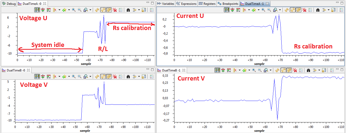
Graph in the attachment is in Volts/Amps, rescaled using Q24 for currents, Q20 for voltages (set appropriately in the graph view as well)

  • Please attach your user.h used for this compilation


  • Thanks, user.h attached.

    Before you comment on the fact, that system is set to 200V/28A - I tried to do the same thing with a 200V power supply delivering 6A for the Rs calibration with pretty much the same result (several magnitudes off). I'm using lower voltages just to keep Rs calculation on for a very long time (~20s, set up in the user.c) without burning anything.

    4571.user.h

  • Michal,

    in your user.h the motor you have active is

    #define USER_MOTOR Induction500W

    That doesn't seem to fit the rest of your posts.


    Which motor are you trying to ID / run?


  • Chris,

    I was trying to set up a system - tried both BLDC as well as ACIM, then found out that the variable scaling is completely off somewhere in the system, while when plotting it in a graph, values itself are perfectly fine. So I replaced a motor with three resistors in a Y configuration to confirm. I can run the test for you not with an induction motor but with three 46ohm resistors if you prefer, or with a small BLDC. I'm trying to fix the Rs measurement, before that is done, motor type is irrelevant - Rs is a very simple type of measurement. Am I right?

  • It's hard to tell you if there are any variable scaling issues w/o knowing more about the motor. There will be cases where you may have to change the FULL_SCALE_FREQUENCY and IQ_VOLTAGE to maximize resolution, etc.

    With your user.h the only warning that comes up is that your Flux (since you have the 3 V/Hz motor set) * FULL_SCALE_FREQUENCY > USER_IQ_FULL_SCALE_VOLTAGE_V

    Of course, you aren't going to really run that motor at 400 Hz, so recalculating with 100 Hz you would need your USER_IQ_FULL_SCALE_VOLTAGE_V > 300.

    With that, there are no errors.


    One thing that IS wrong in your user.h

    #define USER_NUM_ISR_TICKS_PER_CTRL_TICK       (2) 

    you should set this to (1)

    It's possible that your are disturbing the Motor ID states with this SW tick.  I try to only use the HW tick if I need to reduce the PWM rate for the controller:

    #define USER_NUM_PWM_TICKS_PER_ISR_TICK        (1) // ok to use 1, 2, or 3

    #define USER_NUM_ISR_TICKS_PER_CTRL_TICK       (1)      //  try to keep at 1

    #define USER_NUM_CTRL_TICKS_PER_CURRENT_TICK   (1)      // try to keep at 1, no need to sample at a rate and update the controller at a sub rate

    #define USER_NUM_CTRL_TICKS_PER_EST_TICK       (1)  // can reduce this to give effective 2.5 - 20 KHz.  5-10 KHz is usually fine for nearly all applications.


    You are running 20 KHz PWM, sampling every 20 KHz, but only passing through into the control system every 10 KHz..  Then your speed and traj are /20 off of 10 Khz, so they are at 500 Hz.


  • Thank you,

    I did all the recommended modifications. Even reinstalled the latest motorware, loaded the original hvkit project on which my design is based, and did all the hw-dependend modifications again by hand.

    Still, in the variable window I see Rs values like 2e+38.

    What else can I try? How is it possible, that I see the correct values of currents and voltages, and can perfectly replicate Rs value, but the controller cannot? It apparently sees what it's supposed to see (commands proper current, etc). Something tells me that the problem must be something trivial that I was supposed to do, but I did not.

  • Michal,

    you will see values like 2e+38 for Rs when there are no phases attached.  You can test this with our standard kits....air has a huge Rs :) 

    I haven't tried to pull each phase through a large resistor to ground.  I think you will see the exact same thing.  Very high resistance reading.


    Is there no way you can hook up a motor?


  • Yes, air indeed has a high resistance. Maybe I didn't explain it correctly, but I have a motor attached, otherwise I wouldn't even ask why I'm getting so high Rs. Motor has a resistance around 10ohm.

    Since I have one amp flowing through my motor, it can be expected that some load is present :) Please check those graphs in the first post. As I explained before, I get the same values of Rs even with 200V/3A on my 500W motor. But from seeing my graphs it should be clear that there is enough resolution to get a meaningful reading at 20V/1A for a simple Rs reading (we are not talking about Ls and other steps).

    So again, system during ID is reading a correct current, correct voltage, you can use R = V/I formula to get a correct Rs, just the controller is outputting an infinite resistance (or at least 100kOhm or something) from the proprietary controller code. I would debug it myself to see where the problem starts, but I can't..

  • Michal,

    " the controller is outputting an infinite resistance"

    That is not what happens.  All the controller can output is a series of three PWM duty cycles which control a three phase inverter  switching Vbus to ground, through your phase connections (which may be no connected, connected to motor phases, or thorug your resistor network).

    I would double check your ADC configuration in drv and make sure you are actually sampling the correct channels.  To me it looks like you are sampling air.

    "from the proprietary controller code"

    The controller code is not proprietary, it is all there in soure for you in the ctrl files. And you can probe any input or output.

    What you should do is check all the ADC results that are getting passed to the controller / estimator.  One or some of them must be 0000000.


  • Okay, I fixed it.


    " the controller is outputting an infinite resistance"

    English is not my first language. The resulting Rs that controller calculates from inputs is infinite.


    "it looks like you are sampling air."

    I gave all the relevant data in my first post, in there you can clearly see "not air" (in terms of current&voltage).


    "One or some of them must be 0000000."

    None of them were zero (well, except for the third current, which I'm not sampling).


    Problem was that the current has an opposite polarity than is anticipated by the controller, this can be seen in my first post on the current graphs. I found that out by randomly swapping the current sense polarity. Now I can successfully and precisely spin my ACIM motor (didn't do an ID, just guessed the parameters). When the new MotorWare is out, I guess that with a proper ID, I will get a better low speed stability.


    Thanks for the support.

  • Michal,

    I'm very glad you found this.  I was actually thinking about it on my way into work and thought I should bring up the current polarity as a possibility. It caught a few other people who designed their own boards as well.  Wish I would have caught it for you earlier....and my apologies for any mis-communication. Your English is a million times better than any secondary language for me.

    Good luck and have fun with InstaSPIN!

  • Oh, and we did final sign off of MW _12 today.  It will be live Tuesday.

    Please post your experiences with your induction motors.  We tested every induction motor we could get our hands on and feel very good about everything high voltage.  Still another patch for the low voltage / high current motors for MW _13.

  • Thanks,

    I will be more than happy to share my "induction experience", once I establish a good testing platform for higher power motors. Goal is a 20kW induction machine from Siemens (1PH7 line).