This thread has been locked.

If you have a related question, please click the "Ask a related question" button in the top right corner. The newly created question will be automatically linked to this question.

Working through the labs, weird motor identification results

Other Parts Discussed in Thread: INSTASPIN-BLDC, MOTORWARE, BOOSTXL-DRV8301, DRV8301, DRV8312, LAUNCHXL-F28027F, CONTROLSUITE

I've worked my way through labs 1-5b and the motor spins decently at high rpm but at 100 rpm there is next to torque and and I can't get it to run below 80 rpm.

So went back to lab2c and to check the fundamentals and they seem a bit off and I'm not sure what to try next.

The motor is a dental handpiece motor with following spec:

The rotor has one internal magnet so I guess this is one pole pair, right?

Coil resistance is 1.2 Ohms

Inductance 120 uH

Bemf 6.67 mV/(rad/ss)

Max continuous current 2.5 A (rms)

Max peak 10 A (rms for 10 sec)

Max rpm at 24 V is 42 000 rpm

But this what I get in lab2c
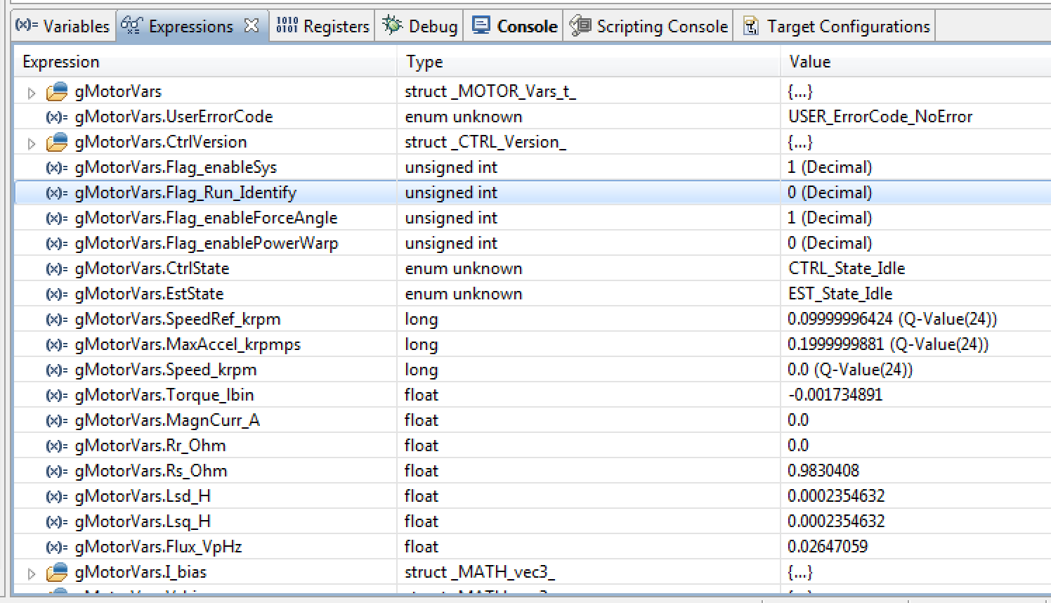
So it looks like resistance is a bit low (measured 0.98 should be 1.2), inductance is way about double of what it should be  high (measure 235 uH should be 120 uH) and the back emf (if I got that right) is about half of what it should be (measures as 26.4 mV/rpm when if my math is correct it should be about 42 mV/rmp).

Is my number of poles wrong or measurement frequency off or what?

My user.h file attached.


8750.user.h

A related question is if I'm on the right track at all using InstaSpin FOC/FAST for this motor?

Should I be concentrating on the InstaSpin BLDC instead?

My goal is to run this at 60 rmp with as much torque as possible of course.

This motor has no sensors and very low or nil saliency so none of the techniques we have found from the literature and tried to figure out the rotor position for commutation have worked so far at such a low rpm.

A related question is if I want to try InstaSpin BLDC do I need to go back to DRV8312EVM board or can I try it out on the BOOSTXL and Launchpad combo?


br Kusti

  • Hi,

    preliminary to changing the AD dividers we hooked up an oscilloscope the measurements signal and motor outputs and what we saw confused us totally!

    See attached scope picture.

    The first one shows the AD input which stays at 1.5 V for 50%of the time and then 50% of the time there is the "double hump" actual signal.

    The second one shows one of the motor phases against ground taken with persistence mode to demonstrate that the duty cycle never goes above 50% .

    But we was expecting to see signals like in the last picture which is screen cap from the InstaSpin User Guide.

    Is there something wrong? If not, what are we seeing/measuring here? As it stands now it looks like we can never get above 50% duty cycles ??!

    I'm pretty sure your code is right so this must be some sort of brain fart on my side or I've changed something in you code (though I don't think I've touched anything in the code, apart from the user.h stuff , only at run time via the Expressions panel) but I can't figure this one out.


    br Kusti

  • in the 2nd part, are you running the motor at near full speed and near full load?  You won't get near full modulation unless you are. 

    I'm not sure what you are trying to show in the first one....you're sampling which signal?


  • Hi,

    sorry I was unclear.

    This was run at 1000 rpm (in lab5b) the mechanical load ranging from 0% to stalling the motor and we captured the PWM of one of the phase in oscilloscope persistence  mode(second picture)  to see the range of the PWM values produced. And it never goes above 50%(and not only approximately 50% but exactly). 

    So my questions are:

    - is this normal/as it should be? 

    - why?

    - if this is the case then we are effectively running the motor max half bus voltage?

    Also if you look at the first picture which is one of the voltage AD inputs, the AD measurement range is 0-3 V but the signal is always below 1.5 V, loosing half of the AD range?

    Again:

    - is this normal/as it should be?

    - why?

    or are we doing something wrong when we measure this?

    br Kusti

  • Can you try another motor? Do you have the small one from our DRV8312 kit?

    Let's see if the inverter HW is still good....we are kind of stumped at what else it could be. 

  • Hi,

    this morning re-installed Motorware 1.01.00.12 to make sure I have not screwed up anything in the software.

    and I connected the BLY172S motor that came with one of your kits.

    On this pristine system I run lab5b and I still can't get more than 50% PWM on any of the motor phase,  see picture below.

    Just to be clear, can you confirm that this is not ok, that I should see more than 50% pwm, up to the 86% limit?

    I can't imagine what kind of hardware problem could cause this, obviously the motor runs and the driver stages are producing PWM, just half of it is missing. So this smell like software problem to me; for example if the PWM counter was not counting up and down, but was only counting up to the period value then something like this could happen. So this could be some sort initialisation issue; apparently everything in the software and hardware works as expected, only half of PWM output is missing….

    But I'm sure you guys have tested this and this really should work out of the can with your kit motor so I'm really confused…to the best of my ability the set up is know exactly as intended...

    Here is the screen cap from the scope showing all the phases (trig on first phase)  the motor running at PWM 45 kH and 1000 rpm captured at persistence mode when I load the motor more and less. Motor and InstaSpin behaves beautifully but half of the PWM is missing. Holding the motor axis pliers I can get half of the pwm go to close to the 86% mark, but this I did not capture.


  • Can you run proj_lab9 or 10, or at least pull out these calculations into 5a (even better) updateGlobalVariables_motor function:

      // read Vd and Vq vectors per units
      gMotorVars.Vd = CTRL_getVd_out_pu(ctrlHandle);
      gMotorVars.Vq = CTRL_getVq_out_pu(ctrlHandle);

      // calculate vector Vs in per units
      gMotorVars.Vs = _IQsqrt(_IQmpy(gMotorVars.Vd, gMotorVars.Vd) + _IQmpy(gMotorVars.Vq, gMotorVars.Vq));


    And then show the value of .Vs during your tests.

    You should see 1.0 when full (sinewave) duty cycle is reached....max speed at sinewave modulation.


  • Thanks I will, but Easter is up on us and next week I'm in London so it will be the week after that.

    While I'm away my colleague Christian may have some questions but I let him speak for himself.

    Meanwhile can you confirm that we should have seen over 50% PWM values?

    Oops I can't run 9 or 10 as they need FPU IIRC, but I can pull those calculations to 5a.

    br Kusti

  • Projects 9 and 10a are both ported for the 2x, they do not require FPU.

    Yes, assuming you are appliyng a voltage vector near 1.0 you should see duty cycles near 75%.


  • Hi,

    I'm back, refreshed from a wedding anniversary trip to London. Recommended, both!

    Ok, so I did what you asked i.e. added this bit of code to lab5a:

    // read Vd and Vq vectors per units
      gMotorVars.Vd = CTRL_getVd_out_pu(ctrlHandle);
      gMotorVars.Vq = CTRL_getVq_out_pu(ctrlHandle);
    
      // calculate vector Vs in per units
      gMotorVars.Vs = _IQsqrt(_IQmpy(gMotorVars.Vd, gMotorVars.Vd) + _IQmpy(gMotorVars.Vq, gMotorVars.Vq));
    

    and I can confirm that 'gMotorVars.Vs' shows values close to 1.0.

    So I started to dig a bit deeper: I went inside the HAL_writePwmData and (over)wrote -0.5 to +0.5 values to the

    pwmData_sat_dc variable and confirmed that I can see 25% / 75% pwm values with the oscilloscope. So this confirms that the hardware works and pwm is correctly set up. 

    I then looked at the gPwmData variable and could see +-86% values in all channels confirming that the SVG generates the correct values. 

    Next I copied the  pwmData_sat_dc values to global debug variable, and hey, they were only showing positive up to 86% or zero values! 

    The obvious suspect is then line 1003 in file hal.h:

    pwmData_sat = _IQsat(pPwmData->Tabc.value[cnt],_IQ(1.0),_IQ(-1.0));

    and indeed if I 'undo' that line by adding after it:

     pwmData_sat=pPwmData->Tabc.value[cnt];

    then the oscilloscope shows me nicely that the whole range of PWM

    values is in use!!

    So the culprit is that line, but what is wrong? 

    Some compiler option or what?

    Remember that this is you example code, clean install, expected to work right out of the box...

    br Kusti

    Here is the whole function that now work for reference:

    static inline void HAL_writePwmData(HAL_Handle handle,HAL_PwmData_t *pPwmData)

    {

      uint_least8_t cnt;

      HAL_Obj *obj = (HAL_Obj *)handle;

      PWM_Obj *pwm;

      _iq period;

      _iq pwmData_sat;

      _iq pwmData_sat_dc;

      _iq value;

      uint16_t value_sat;

      for(cnt=0;cnt<3;cnt++)

        {

          pwm = (PWM_Obj *)obj->pwmHandle[cnt];

          period = (_iq)pwm->TBPRD;

          pwmData_sat = _IQsat(pPwmData->Tabc.value[cnt],_IQ(1.0),_IQ(-1.0));

         pwmData_sat=pPwmData->Tabc.value[cnt];

          pwmData_sat_dc = _IQmpy(pwmData_sat + _IQ(1.0), _IQ(0.5));

          value = _IQmpy(pwmData_sat_dc, period);

          value_sat = (uint16_t)_IQsat(value, period, _IQ(0.0));

          // write the PWM data

          PWM_write_CmpA(obj->pwmHandle[cnt],value_sat);

        }

      return;

    } // end of HAL_writePwmData() function


  • REPOST to fix formatting for easier reading:

    Hi,

    I'm back, refreshed from a wedding anniversary trip to London. Recommended, both!

    Ok, so I did what you asked i.e. added this bit of code to lab5a:

    // read Vd and Vq vectors per units
    gMotorVars.Vd = CTRL_getVd_out_pu(ctrlHandle);
    gMotorVars.Vq = CTRL_getVq_out_pu(ctrlHandle);
    
    // calculate vector Vs in per units
    gMotorVars.Vs = _IQsqrt(_IQmpy(gMotorVars.Vd, gMotorVars.Vd) + _IQmpy(gMotorVars.Vq, gMotorVars.Vq));
    

    and I can confirm that 'gMotorVars.Vs' shows values close to 1.0.

    So I started to dig a bit deeper: I went inside the HAL_writePwmData and (over)wrote -0.5 to +0.5 values to the

    pwmData_sat_dc variable and confirmed that I can see 25% / 75% pwm values with the oscilloscope. So this confirms that the hardware works and pwm is correctly set up.

    I then looked at the gPwmData variable and could see +-86% values in all channels confirming that the SVG generates the correct values.

    Next I copied the pwmData_sat_dc values to global debug variable, and hey, they were only showing positive up to 86% or zero values!

    The obvious suspect is then line 1003 in file hal.h:

    pwmData_sat = _IQsat(pPwmData->Tabc.value[cnt],_IQ(1.0),_IQ(-1.0));

    and indeed if I 'undo' that line by adding after it:

    pwmData_sat=pPwmData->Tabc.value[cnt];

    then the oscilloscope shows me nicely that the whole range of PWM

    values is in use!!

    So the culprit is that line, but what is wrong?

    Some compiler option or what?

    Remember that this is you example code, clean install, expected to work right out of the box...

    br Kusti

    Here is the whole function that now work for reference:

    static inline void HAL_writePwmData(HAL_Handle handle,HAL_PwmData_t *pPwmData)
    
    {
    uint_least8_t cnt;
    HAL_Obj *obj = (HAL_Obj *)handle;
    PWM_Obj *pwm;
    _iq period;
    _iq pwmData_sat;
    _iq pwmData_sat_dc;
    _iq value;
    uint16_t value_sat;
    
    for(cnt=0;cnt<3;cnt++)
    {
    pwm = (PWM_Obj *)obj->pwmHandle[cnt];
    period = (_iq)pwm->TBPRD;
    pwmData_sat = _IQsat(pPwmData->Tabc.value[cnt],_IQ(1.0),_IQ(-1.0));
    pwmData_sat = pPwmData->Tabc.value[cnt]; // UNDO PREVIOUS LINE!!!
    pwmData_sat_dc = _IQmpy(pwmData_sat + _IQ(1.0), _IQ(0.5));
    value = _IQmpy(pwmData_sat_dc, period);
    value_sat = (uint16_t)_IQsat(value, period, _IQ(0.0));
    // write the PWM data
    PWM_write_CmpA(obj->pwmHandle[cnt],value_sat);
    }
    return;
    } // end of HAL_writePwmData() function

  • there is a compiler bug for IQsat in 6.2.0-6.2.2, but I thought you confirmed you were on compiler 6.2.3+ already


  • Kustaa Nyholm said:
    My goal is to run this at 60 rmp with as much torque as possible of course.

    60 RPM on a 42 KRPM motor with this small of Bemf is going to be challenging.

    Kustaa Nyholm said:
    A related question is if I'm on the right track at all using InstaSpin FOC/FAST for this motor?

    Should I be concentrating on the InstaSpin BLDC instead?

    IS-BLDC will be MUCH worse at low speed. FAST is the best thing on the market for slow speed...but is dependent on the Flux and current/load. You are on the edge.

    Kustaa Nyholm said:

    A related question is if I want to try InstaSpin BLDC do I need to go back to DRV8312EVM board or can I try it out on the BOOSTXL and Launchpad combo?

    There is no SW for IS-BLDC on LP+BP.  If you ported this over from controlSUITE you could do the basic commutation, but there isn't a I-total signal so you can't do any current control.


  • Ah, that would explain this (what else could it be, in retrospect).

    I don't think I said (probably should have) what version I had, the CCS is 5.5.0.00077 … I'm pretty sure I installed this just one or two months ago when this virtual machine was created. Anyway I will install the latest when I get back to office tomorrow.

    Thanks for help again.

    br Kusti

  • REPOST, managed to respond to some earlier part of this thread:

    Ah, that would explain this (what else could it be, in retrospect).

    I don't think I said (probably should have) what version I had, the CCS is 5.5.0.00077 … I'm pretty sure I installed this just one or two months ago when this virtual machine was created. Anyway I will install the latest when I get back to office tomorrow.

    Thanks for help again.

    br Kusti

  • CCSv5.5 ships with the compiler that has the bug...you have to update per the sticky on the 1st page.

  • Thanks, will do that first thing tomorrow and then redo the low rpm tests we did earlier and then proceed to improving the AD-conversion resolution.

    Thanks again, I'll report back and confirm this and mark this as answered.

    If and when we hit new obstacles I will then open a new thread, this has been going on too long for now...

    br Kusti

  • Hi,

    ok, this just to confirm that upgrading the compiler solve the problem of half of the PWM range missing.

    Still can't get the motor to work as required but I'll start an other thread.

    br Kusti