This thread has been locked.

If you have a related question, please click the "Ask a related question" button in the top right corner. The newly created question will be automatically linked to this question.

Working through the labs, weird motor identification results

Other Parts Discussed in Thread: INSTASPIN-BLDC, MOTORWARE, BOOSTXL-DRV8301, DRV8301, DRV8312, LAUNCHXL-F28027F, DRV8301-69M-KIT, CONTROLSUITE

I've worked my way through labs 1-5b and the motor spins decently at high rpm but at 100 rpm there is next to torque and and I can't get it to run below 80 rpm.

So went back to lab2c and to check the fundamentals and they seem a bit off and I'm not sure what to try next.

The motor is a dental handpiece motor with following spec:

The rotor has one internal magnet so I guess this is one pole pair, right?

Coil resistance is 1.2 Ohms

Inductance 120 uH

Bemf 6.67 mV/(rad/ss)

Max continuous current 2.5 A (rms)

Max peak 10 A (rms for 10 sec)

Max rpm at 24 V is 42 000 rpm

But this what I get in lab2c

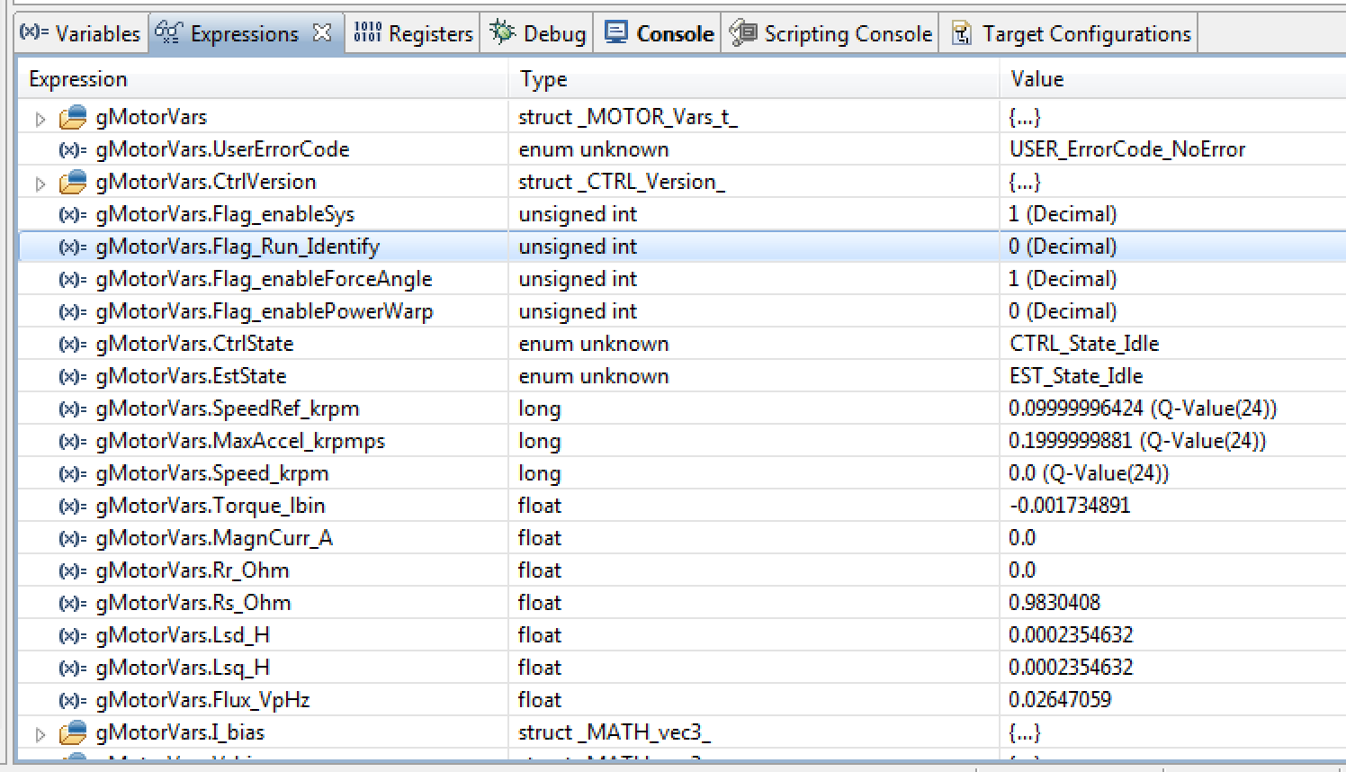
So it looks like resistance is a bit low (measured 0.98 should be 1.2), inductance is way about double of what it should be  high (measure 235 uH should be 120 uH) and the back emf (if I got that right) is about half of what it should be (measures as 26.4 mV/rpm when if my math is correct it should be about 42 mV/rmp).

Is my number of poles wrong or measurement frequency off or what?

My user.h file attached.


8750.user.h

A related question is if I'm on the right track at all using InstaSpin FOC/FAST for this motor?

Should I be concentrating on the InstaSpin BLDC instead?

My goal is to run this at 60 rmp with as much torque as possible of course.

This motor has no sensors and very low or nil saliency so none of the techniques we have found from the literature and tried to figure out the rotor position for commutation have worked so far at such a low rpm.

A related question is if I want to try InstaSpin BLDC do I need to go back to DRV8312EVM board or can I try it out on the BOOSTXL and Launchpad combo?


br Kusti

  • InstaSPIN-BLDC will perform much worse for slow speed.  

    What is your bus voltage?

    The flux on these types of motors are very low as you will note, so continuous ultra low speed is impossible with observer approaches. 60-180 RPM is probably about the best you will do. Look how small the Bemf at 1Hz will be in relation to your voltage scaling (26V).  When you are resting low speed performance set ForceAngle to 0. You will then still need to tune your speed loop. You can do this at 0 speed.  What is your low speed goal?

    Once you find the lowest reasonable speed you put this setting in user.h and use a ForceAngle frequency 2x this speed, enable force angle all the time, and it will give you best results possible for what you are trying to do. You will also get slight enhancements by perfectly scaling the HW sensing to your motor.

    Your parameters look good and R/L and Isc are expected for this motor. It's not particularly low inductance, so I'm curious if 2a also worked?

  • I'm running the BOOSTXL from 24 V lab supply atm.

    I know this is a challenging motor but I have reference black box that does it at 60 rpm and I need to match that. If necessary I can add more gain to the AD inputs if that would help.

    I think 2a worked but I'll go back and check and come back to you.

    Is my interpretation of the number of poles correct ie one pair?

    What about the bemf and inductance being off by a factor of half/two, am interpreting this incorrectly or what, or it does not matter?

    br Kusti

  • Hmm, lab2a is not available with this BOOSTXL/Launchpad combo …I'll go for 2b ?

  • Ok, I re-run lab2b …don't know what to make of it, maybe I did something wrong.

    There is first a hum but no movement, then the motor speeds up but holding

    it in my hand I feel it is a bit rough, at some point it starts to run erratically.

    When it stops the values I get are pretty much as in my previous post and attachements

    except the inductance now is measured as double of what I got previously.

    gMotorVars.Lsd_H float 0.005192941 

    br Kusti

  • Our parameters are line to neutral, so half of line to line. Also, datasheets typically aren't so accurate. Further, inductance is not a static value. It changes with speed and load. 

    Have you tuned your speed controller at all?  Turn OFF ForceAngle and try. You can also run in torque mode and load the motor to near full to test the limits. 

    If your motor makes 1 rev per sec with 60 RPM or 2 rev with 120 RPM you have chosen your poles correctly. I would expect this motor to have 2 poles, for 60krpm that is 1khz electrical. Very reasonable. 

    And your Bemf will produce just over 20V at that speed, just under the Vbus. 

  • Ok, stick with 2c for ID. 

    BTW, I think about 60 RPM is best you will do as is. If you were able to dynamically gain up the voltage signals at very low speed you could do better, probably 15 rpm or so. Or, have them make your motor with more flux. 

    Or add more poles (but then you would need more voltage ti hut top mechanical speeds).

  • Ok, thanks for the clarification and confirmations.

    Yes I did some tuning but I'm just learning the ropes so I will get back to it armed with your hints.

    But now for something completely different … there is a lovely little red -67 Mustang waiting for some brake lines so I need to hurry to the shop…;)

    I'll be back tomorrow.

    cheers Kusti

  • Ok,

    went through the labs 2a - 5b this morning, this time USER_PWM_FREQ_kHz = 60 and USER_MOTOR_FLUX_EST_FREQ-Hz. Got a little different, maybe a bit closer to theoretical values, for the coil inductance , resistance and back emf values.

    I verified that the  gMotorVars.Speed_krpm value reprsents the motor rpm reasonably (don't have rpm meter atm, will have access to proper brake, torque and speed meter starting monday).

    At 1000 rpm the motor seems to run smootly and gMotorVars.Speed_krpm tracks the gMotorVars.SpeedRef_krpm value so basically the feedback loop is working. The indicated speed gMotorVars.Speed_krpm fluctuates quite a bit (i would say +- 5% everytime the Eclipse realtime debugger screen is updated).

    There is a reasonable torque when I apply load to the rotor but I cannot get the system to put more than ~0.9 Amps though the I've set the USER_MOTOR_MAX_CURRENT = 3.0.

    At 200 rpm the motor runs, not sure how smoothly but reasonably, but the torque is very small and the current will not rise above 0.2 Amps at which point the motor stall or loses sync with the commutation and I get a back and forth rotor motion.

    I've played with I and P parameters of both the speed and current loops and I did the calculations in labs 4 and 5 and the rehearsals but I'm not sure I really learned much from it.

    I tried gMotorVars.Flag_enableForceAngle =0 and 1, with 0 it performs even more poorly.

    I think my next goal should be to able to get full current/max torque at reasonable speed and then try to work my way to the low rpm, but I don't know how to proceed.

    One more thing. 

    It looks like the speed caps at  gMotorVars.Speed_krpm = 13 though by the sound of it I think the motor runs at least twice as fast, this is probably a scaling issue.

    br Kusti

  • please

    Option --> click to add file attachment --> user.h you are using


  • Here you go, I thought I had done that before, but then again this mornings exercises changed a few bits.

    br Kusti

    user.h
  • You have your PWM at 60 kHz, with a HW tick of (3), which means you are trying to run your current control and estimator at 20 KHz. This will overflow your interrupt very likely (you can check this in proj_lab3).

    For this 60 MHz device go down to 45 KHz PWM and keep all other settings as is. This will run current and EST at 15 KHz, which will already be using most of your interrupt MIPS.  You are only trying to run this motor to about 800 Hz, so you should be fine with even 10 kHz rates on current and estimator.  Also, your short circuit current is only about 12A and your inductance is quite reasonable at 340 uH so there is no reason you need to PWM at even 45 KHz.  20 should be plenty.

    So if I were you I would use

    PWM (20)

    PWM_TICKS (2) // this gets you to 10 KHz ISR

    ISR (1) // keeps CTRL rate = ISR rate = 10 KHz

    _CURRENT_TICK (1) // 10 KHz

    _EST_TICK (1) // 10 KHz

    SPEED (10) // effective 1 KHz

    TRAJECTORY (10) //effective 1 KHz


    Make sure when you run you keep OffsetCalc enabled until you have updated your I and V offsets in user.h per proj_lab3


    "It looks like the speed caps at  gMotorVars.Speed_krpm = 13 though by the sound of it I think the motor runs at least twice as fast, this is probably a scaling issue."

    Your speed commands/estimates are limited to FULL_SCALE_FREQ * 1.99 = 800 Hz * 1.99 = nearly 96 KRPM with 1 pole pair machine.  So it's not that...


  • Ok,

    I changed things as follows (diff) but now nothing much happens when I enable and run (lab5b) so

    I tried lab2b but that too refuses to do much anything….

    ~/Downloads/user.h /Volumes/C/ti/motorware/motorware_1_01_00_12/sw/solutions/instaspin_foc/boards/boostxldrv8301_revB/f28x/f2802xF/src/user.h
    146c146
    < #define USER_PWM_FREQ_kHz (20) //30.0 Example, 8.0 - 30.0 KHz typical; 45-80 KHz may be required for very low inductance, high speed motors
    ---
    > #define USER_PWM_FREQ_kHz (60.0) //30.0 Example, 8.0 - 30.0 KHz typical; 45-80 KHz may be required for very low inductance, high speed motors
    176c176
    < #define USER_NUM_PWM_TICKS_PER_ISR_TICK (3)
    ---
    > #define USER_NUM_PWM_TICKS_PER_ISR_TICK (2)
    198c198
    < #define USER_NUM_CTRL_TICKS_PER_SPEED_TICK (15) // 15 Typical to match PWM, ex: 15KHz PWM, controller, and current loop, 1KHz speed loop
    ---
    > #define USER_NUM_CTRL_TICKS_PER_SPEED_TICK (10) // 15 Typical to match PWM, ex: 15KHz PWM, controller, and current loop, 1KHz speed loop
    203c203
    < #define USER_NUM_CTRL_TICKS_PER_TRAJ_TICK (15) // 15 Typical to match PWM, ex: 10KHz controller & current loop, 1KHz speed loop, 1 KHz Trajectory
    ---
    > #define USER_NUM_CTRL_TICKS_PER_TRAJ_TICK (10) // 15 Typical to match PWM, ex: 10KHz controller & current loop, 1KHz speed loop, 1 KHz Trajectory

  • doesn't do much of anything...that's not very descriptive.

    please just attach your user.h again so I can check for mistakes.


  • Ah, sorry, I thought the diff would be the easiest way to check what I changed … ok, I will attach user.h but not right now as my Windows installation just blew a fuse when I tried to restart it … strong words.

    br Kusti

  • Ok, I'm back.

    Please find the new user.h file attached.

    Meanwhile I had to reboot everything and I went back to the user.h that worked before I made the changes you suggested and now nothing works!

    I load lab05b and go through the motions and when I enableSys=1 and Run_Identity= 1 the gMotorVars.CtrlState goes to CTRL_State_OnLine and some hissing sound comes from the motor but then nothing. 

    Looks like the embedded software crashed or something because then I set run=0 and sys=0 nothing happens and the hissing sound from the motor continues.

    Outch.

    br Kusti

    user-new.h
  • you didn't change what I told you to correctly.

    try attached with proj_lab2b, and if the parameters don't look good try proj_lab2c.

    then add the ID'd parameters to user.h and try proj_lab5a (torque) or 5b (speed).


    During ID the motor starts spinning during RampUp and keeps spinning (with no strange noise) until ID is finished, correct?


    user-new.h
  • Thank you very much.

    Yeah, I was afraid I changed something wrong.

    As I said I went back to the original user.h and lab2 and could not make it work so I called it a day in my frustration. 

    So I'll be back tomorrow again.

    br Kusti

  • Ok, not sure what happened yesterday, probably my thumb was in the middle my palm though I got the impression that if I just replace user.h in the Windows File Exploder it is possible to have a situation in which Eclipse/make does not recognise the file as changed. Eclipse does some cacheing there and this usually cleared by doing a Refressh in the the Eclipse Project Explorer, but looks to me that due to the way the lab projects are organised the user.h file is not actually included in the project and so Eclipse does not recognise that it has changed.

    Anyway I'm back in business.

    I redid the labs 2b,3a and 5b, ie have new (but not much different) values for resistance,inductance, back emf and biases.

    Nothing much has changed, I'm still wondering the same issues:

    at 1000 rpm I cannot get more than 1 Amp by loading the motor axis, I get up to 1 Amp and then it stalls.
    at 200 rpm I can barely get 0.1 Amps.

    While playing around I noticed that depending on weather I have a any load or not on the motor I can not get faster than 3-4 krmp. When I try to do that some sort of run away or windup happens, first the motor slowly  accelerates towards the target rpm and then suddenly hits the full speed and the speed_krmp shows a varying value of about 13 indicating 13 krmp but by the sound of it the motor is doing twice of that, will know for sure on monday when I get the meter.

    My next priority is to work to the the 200 rpm work with full torque, any ideas?

    I'll attach the updated user.h file , though that is basically what you supplied with those things mentioned in the labs updated.

    br Kusti

    user.h
  • you did not change correctly the things I suggested.

    your clock rates are completely wrong.

    let's use attached....

    do you know enough about this motor to think these values are close?

    #define USER_MOTOR_Rs                   (1.019281)
    #define USER_MOTOR_Ls_d                 (0.0003459794)
    #define USER_MOTOR_RATED_FLUX           (0.02616818)

    They give reasonable R/L and Isc values.

    You may want to play with taking these lower. Try 0.3 to startout and see if the Rs value is lower...make sure your motor still starts up during Ramp_Up and continues until IDis finished.  If it doesn't Ramp_Up increase by 0.1 until it does.

    #define USER_MOTOR_RES_EST_CURRENT      (1.0)
    #define USER_MOTOR_IND_EST_CURRENT      (-1.0)


    user-new.h
  • Hi Chris,

    something not computing here, yesterday you wrote  "you didn't change what I told you to correctly.try attached..."

    and that's what I think I did, I'm pretty sure as I double checked and diffed the file I got from your post's attachment.

    And now you say I did not change things correctly, but it was your file ?… anyway I'll try your attached file and see

    where that get's me.

    You ask if the values are close and I think they are except maybe the inductace, see below:


    #define USER_MOTOR_Rs                   (1.019281)        

    The motor spec says  1.2 Ohms so that is reasonably close.

    #define USER_MOTOR_Ls_d                 (0.0003459794)

    The spec says 120 uH but your comment last time was that this depends on the load on the motor


    #define USER_MOTOR_RATED_FLUX           (0.02616818)

    The motor spec says 6.67 mV/(rad/s)  which my math says is 42 mV/r which is twice what gets

    measured but you commented that this ok as your values are ref half bus voltage and thus scaled by 0.5

    or maybe I've miss interpreted something.

    Ok, I will now download your attached  file and see where that takes me.

    Thanks again for your help in this matter.

    br Kusti


  • Ok, tried that file, and the performance is not better or maybe slightly worse.

    At 200 rpm the speed is all over the place from 170 to 230 on every screen update, no torque loading does not get the current up higher than 100mA max before it stalls.

    At 1000 rpm the speed regulation is much better than at 100 rpm much more torque and currents up to 800 mA before stalling but nowhere near the 3 Amp I put in the user.h as max current for the motor.

    Trying to get 4000 rpm reaches about 3500 and then suddenly goes to very high speed the Speed_krmp reads back as 13.5 ie 13500 rpm.

    Will now check back your post, there was something you suggested I should try.

    br Kusti

    This is with the default PI speed and current loop factors.


  • I tried:

    #define USER_MOTOR_RES_EST_CURRENT      (0.3)

    #define USER_MOTOR_IND_EST_CURRENT      (-0.3)

    but that did not make a difference.

    br Kusti

  • Rs: if your spec says 1.2 then our 1.02 is a bit high, I woulld expect closer to 0.6 from our ID process.  Using 0.3A for RES_CURRENT still produced 1.02 ohm?

    Low speed performance is dependent on Rs estimation (as well as speed loop tuning).

    "At 200 rpm the speed is all over the place from 170 to 230 on every screen update"

    The Speed PI controller is not tuned with InstaSPIN-FOC.  You have to tune this manually and will depend on the inertia of your system.


    Your Ls is worrisome.  If your spec is 120uH I would expect to ID around 60uH with InstaSPIN.  345uH is a gross inaccuracy.  Ls is dominant at high speed, but being this far off will cause some low speed issues.

    Why don't you try updating some different values in user.h and bypassing Motor ID: 60uH, 120uH, 180uH

    #define USER_MOTOR_Ls_d                 (0.000060)
    #define USER_MOTOR_Ls_q                 (USER_MOTOR_Ls_d)

    See if performance improves.

    BTW - your datasheet Rs / Ls = 10,000 Hz.  That is really high...but often these motors are designed like that..


    Flux:
    Your 6.67 mV/rad-sec = 0.042 V/Hz, so our value is reasonable. 

    BTW - your datasheet short circuit current = 55.6 A, which is reasonable. 

    If we reverse solve for the Ls to use based on our ID'd flux and 55.6A it would give you 74uH.

    So I would try

    #define USER_MOTOR_Ls_d                 (0.000074)
    #define USER_MOTOR_Ls_q                 (USER_MOTOR_Ls_d)


    Looking at your issues with not geting enough current, I think having a new lower Ls will increase your bandwidth in the curren controllers, making them react faster. I also recommend setting this higher than the 3A you were using.

    #define USER_MOTOR_MAX_CURRENT          (10.0)

    BTW - are you using proj_lab2c to ID this motor?  You will absoutely have to use 2c based on the R/L and low flux / low Ls.  None of the other projects will work.

    Give that a try...I feel success is close.

  • Thank you very much for the very thorough look at my values, I will digest this over the weekend and continue work on this on Monday, have great weekend.

     br Kusti

  • Hi,

    now I've got a good setup with digitally controlled dynamometer, torque sensing and rpm measurement.

    I've gone back to lab5a to see that I can control the current.

    I went with your suggestions and set:

    #define USER_MOTOR_Rs                   (1.019281)

    #define USER_MOTOR_Ls_d                 (0.000074)

    #define USER_MOTOR_Ls_q                 (USER_MOTOR_Ls_d)

    and now I can get 12 Nmm @ 1 Amp which is in line with this motor spec,

    the rpm is a tad off, gMotorVars.Speed_krpm = 1.0 when the dyno says aprox 950 rmp

    but event though I set qRef_A long = 2.0 I cannot get the motor to use more than 1 Amp,

    I try to brake it some more it will just stall.

    So what is limiting my torque, I would have the PI control would have given me all its got?

    br Kusti

  • considering the SpeedEst and dyno don't quite agree, and you stall (estimator may be losing sync) I'd guess the Ls value took a guess on is not correct.

    Try lowering this to say 40uH (lower Ls is always better than having too high of Ls) and see if the SpeedEst and torque capability improve.


  • Thanks Chris,

    when I tried to lower the inductance I got "gMotorVars.UserErrorCode == USER_ErrorCode_ctrlFreq_Hz_Low"

    so I scaled the resistance down from 1 -> 0.5 but the motor has trouble starting it stutters and I may have to give it a spin to get up to speed, and when it does the current and torque are little bit more than half of what it was with the higher (70uH) inductance and resistance (1 Ohm) values.

    I also tried to keep the resistance at 1 Ohm while lowering the inductance to 40 uH and compensating by increasing 

    USER_PWM_FREQ_kHz to 90 but then nothing happens when I try to run the motor, no error, no nothing, I guess I'm way over acceptable CPU usage with that frequency.

    To summarize, so far 1 Ohm 70 uH  at USER_PWM_FREQ_kHz 45 has produced the best performance, at about 1000 rpm the motor starts nicely and  rpm is about what it should be loaded or not, the only issue is that I get less than half of the torque/current from the motor before it stalls when I load it.

    br Kusti

  • Hi,

    just to verify the motor spec we measured the motor resistance and inductance and got back about 0.95 Ohms and 60 uH. The inductance value was thus about half what the spec says.

    These values are also very close to what we have put into the user.h as you can see from the above.

    And it performs nice (as explained in my previous post) except I can't get the max current / torque.

    So how do I find out what is limiting the current? Do dig into the code and debug where the control loop hits the ceiling or what?

    Can you also confirm me if the  USER_MOTOR_Ls_d value is the single coil inductance or inductance between (start config) motor wires?

    We measured 120 uH from wire to wire so coil inductance is 60uH and so we put should set

    #define USER_MOTOR_Ls_d                 (0.000060)

    is that correct?

    br Kusti

  • Yes, that's correct. I'm traveling but will try to answer. 

    1. Can you try project 5a to take speed loop out of equation? You can directly command any Amperage up to your IQ value.

    2. Please look at the flux value that is being returned at different speeds and as the motor gets loaded. It needs to stay stable, and should never go 40% lower or higher than the value in user.h.  If this is moving it is because your filter pole doesn't match the real hardware pole well enough. 

  • Hi, thanks,

    ok, thanks, I did the following experiment.

    I loaded lab05 and set  Iqref_A=4 without a load the motor run 15000 rmp and power supply current was 0.5A.

    I then turned on the dynamometer brake and increased the load the power supply current peaked at 1.8 A which

    was at about 2400 rpm. I also observed the Flux_VpHz at the same time and without load the value was 0.0266 and with the maximum load it was 0.037, it seems to increase as the motor load goes up.

    I also observed that as the motor warms up from ambient 25 C to luke warm 45-50 C the max current I can get seems to drop.

    Finally I changed  Iqref_A=10 and repeated above and the max current was still only 1.83 A

    br Kusti

  • I meant to write lab05a of course as you suggested.

    br Kusti

  • PING

    I've made some headway and solved some of the issues that bothered me.

    I've now implemented the 'online rs calbration' as per instructions in the

    InstaSpin User Guide (16.1) and I can now get decent torque consistently

    at 1000 rpm. Previously my results were very confusing but I diagnosed

    that to be problem with the motor very quickly heating up when loaded,

    after all it is only about 20 mm x 40 mm and can consume up to 80W.

    Now with the 'on line calbration' the behaviour is more or less consistent

    and the back emf value does not seem change that much as I load the motor.

    I still can't get full current/torque but I've diagnosed that to the 86% limit on

    PWM. If I got it correctly I would need to implement the current reconstruction

    code, seems simple, but at this point I don't think I will bother.

    But now I could do with some pointers on how to proceed. I currently cannot

    get the motor to run below 300 rpm, when I try to do that the motor loses

    commutation for lack of better description, ie it just rocks back and forth. 

    How do I diagnose this problem?

    Do I need more gain voltage measurement / AD conversion chain, remember this

    motor only produces about 26 mV/Hz….

    br Kusti

  • Kustaa Nyholm said:

    I would need to implement the current reconstruction

    code, seems simple, but at this point I don't think I will bother.

    This is implemented in proj_lab10

    Kustaa Nyholm said:

    I currently cannot

    get the motor to run below 300 rpm, when I try to do that the motor loses

    commutation for lack of better description, ie it just rocks back and forth. 

    How do I diagnose this problem?

    Do I need more gain voltage measurement / AD conversion chain, remember this

    motor only produces about 26 mV/Hz….

    1. make sure ForceAngle is DISABLED.  You want to test how low FAST feedback is stable.

    2. 300 RPM = 5 Hz for 2 poles = 5 Hz * 0.026 V/Hz = 0.13V on a 0-26V scale, or 0.5%.  It's about 21 counts of your 4096 counts in a 12-bit ADC.  You are certainly in the noise floor wouldn't you thinki?


  • Hi Chris,

    thanks for answering.

    Yes I had spotted lab10a but as I'm now getting about 1 ~20 mNm @ 1.8 Amps  with max pwn 86% I'm confident I can get the specified 24 mNm at the specified 2.5 Amps with 100% pwm or,which is actually the case, we will be using 32 VDC bus voltage in the actual product. 

    And yes I thought so too that we are at the noise floor, just wanted a confirmation and canvas if there is anything worth thinking about / consider at this point before we get soldering iron out and upgrade the measurement system. 

    Speaking of which, I did not easily spot the BOOSTXL board full schematics, is that available, I think at this stage we would like to just modify the board to boost the voltage measurement and maybe upgrade the FETs or what ever is limiting us from running this kit at higher than 24 VDC. If I can just convince myself that we can run this motor at 100 rpm or better yet a 1 Hz as the FAST manual boast then we can move forward and prepare a board for this.

    br Kusti

  • HW zip is on this page

    http://www.ti.com/tool/boostxl-drv8301

    You need bits of resolution to reach 1 Hz with these motors . Minimize the ADC_V and IQ_V as much as possible. Beyond that you would need to use variable gaining. You can do this with the drv8301, boosting the signal at low speed. Of course you will have to manage this in your SW scaling to make sure the algorithms get a real value. We have always had this on our list to do as an example....fun project. 

    BTW we run large Bemf motors and high voltage induction at 0.25 Hz. All about bits of resolution on the flux. 

  • Brilliant, thanks.

    And thanks for the encouraging words.

    I will dig into this deeper on Monday, have a great weekend!

    br Kusti

  • Kustaa Nyholm said:
    I think at this stage we would like to just modify the board to boost the voltage measurement and maybe upgrade the FETs or what ever is limiting us from running this kit at higher than 24 VDC.

    You can simply change out the voltage dividers for Vbus and 3 phase voltages and use a higher voltage. Of course, change the user.h scaling settings for voltage also. The limit is the 60V for the DRV8301 and whatever the FETs are....I think you can push them to 48V no problem. The guys on the Motor Drive forum know best.

    Just realize that with the same motor you are using, if you double the ADC voltage ragne from 26.x V to 52.x volts, you just halved your resolution, so your low speed performance will get worse.

    This may be a time where you want to look at running your phase voltages through a PGA. Unforatunately

    1. the DRV8301 only has 2 (there is a new chip coming that will have 3)

    2. on this HW we of course use the PGAs for current instead of voltage

    But it is technically feasible to implement if had the desire.


  • Thanks for the above, yes I realise that increasing the voltage will reduce our resolution.

    Right now we are not going to increase the voltage as I'm confident that it can be done when needed,

    right now I just want to check the low speed performance.

    Couple of things / clarifications would come handy.

    By PGA you mean Programmable Gain Amplifiers, right? Yes, when we go for the final design that is the way to go I'm sure given our needs, but right now just want to look at the 100 rpm range.

    Is the PWM / ADC timing that InstaSpin uses  spelled out somewhere, I've tried to trace all detail out from the software but it is so easy to make a mistake so it would be nice if the pwm waveforms and adc sampling points and their relation ship to the software would spelled out somewhere. For example I've yet to figure out where the voltage are read, the initialization references ADC trigger for all channels to EPWM1 but surely they cannot all happen on all channels at the same time, I mean you can only get meaningful voltage from the coil that is not energised at the moment, right? I must be missing something...

    Releated my co-worker thinks that instead of measuring voltage agains ground it would be better measure the between phases and convert them in software to values that the CLARKE transform expects. My worry is that I've not seen any examples of that …so is this something that has been done, is there any advantage, are there any examples or applications notes…surely if that is a good idea someone must have done it before...

    br Kusti

  • Yes, PGA = programmable gain amplifier.  We have them on a device like F2805x.  Typically you use them for current sampling (to remove the OPA from the PCB), however in your case I think they would be best served to sample the voltage.  We think this will allow significantly lower speed operation of low flux motors.

    Regarding 100 RPM...you want this unloaded or with load?  What has helped the most is actually using InstaSPIN-MOTION and the SpinTAC controller. This typically allows for control at a low speed (and sometimes another /2, or / 4 slower) than just the PI speed controller that must be manually tuned.

    The PWM/ADC timing is quite simple.

    The ePWM1 module is the trigger for all conversions, and they happen sequentially.

    see hal.h

    HAL_readAdcData


    Kustaa Nyholm said:
    Releated my co-worker thinks that instead of measuring voltage agains ground it would be better measure the between phases and convert them in software to values that the CLARKE transform expects

    No, this is not recommended. Please use phase to ground as our examples show.


  • Hi Chris,

    thanks, 100 rpm or preferably (60 rpm if possible) under load and without load.

    Re measuring the coil voltages: In the low rpm

    region the coil voltages and back emf are around 12 V +- some small

    voltage,  say for the discussions sake +-1 V.

    Now if we measure against ground we scale the AD from 0 .. 13 V to

    maximize our resolution, but then our signal that we really are interested in

    is just 1/13 of the AD range..?

    Or are you saying that we should refer the AD to a virtual ground at +12 V?

    br Kusti

  • …or, maybe the penny dropped, what is the state of the B and C switches in the bridge when we measure voltage on A, is that the key to my mental block? If B (or C) is grounded then the coil voltage A is referenced to ground?

  • All samples are taken sequentially at Timer =0

    For low side shunt topologies (all of our kits) this is the center of the low side on PWM pulse. So yes, each phase is connected to ground, assuming the pulse on time is long enough to capture all samples. 

  • Ok, I think I understand now how current and voltages are measured. 

    As discussed we probably need to increase our resolution and indicated the the

    voltage resolution is what we need to improve. For this test only , just to see if we can do 100 rpm,

    we can for example double the resolution by changing the voltage dividers from 0-24 V to 0-12 V

    and half drive voltage to 12 V, is that correct?

    But if I understand correctly, current measurement also plays a role in how FAST estimates the rotor angle,

    so how about that resolution, do we need to improve that too?

    Which is more important?

    br Kusti

  • Kustaa Nyholm said:

    we can for example double the resolution by changing the voltage dividers from 0-24 V to 0-12 V

    and half drive voltage to 12 V, is that correct?

    remind me what your flux is measured as? 


    Kustaa Nyholm said:

    But if I understand correctly, current measurement also plays a role in how FAST estimates the rotor angle,

    so how about that resolution, do we need to improve that too?

    Which is more important?

    Yes, current plays a role, but voltage is much more important. You should design your current sense to measure just over your peak-to-peak current under full load.

    Also, if your motor is heating up the Rs online is critical for low speed performance.

  • Hi Chis,

    and thanks. The  flux is 26 mV/Hz and the motor does heat up rapidly but the Rs online seems to help a lot.

    br Kusti

  • your flux is about 2/3 that of the small motor we include in the DRV8312 kit.  This can run down to about 2-3 Hz with ok performance. It will probably be tough to get to 1 Hz with this scaling though, even if you reduce the bus voltage.

    How much have you tuned your speed controller? That is as much of a limiting factor.

    For example, I am running a power steering motor with BOOSTXL-DRV8301, and the default speed controller gains come up at like Kp = 6 and Ki = 0.06

    For zero and low speed performance I need to go to Kp = 60+ and Ki = 2+ for stiffer control.  If you have the F28069M controlCARD this is where I've seen the SpinTAC controller in InstaSPIN-MOTION be a big benefit. It gets you to lowest possible speed much more quickly and better than the PI control.  Then, that tuning works across the whole speed range.  EIth my power steering motor I can make it very stiff at 0 speed, but then I have to turn all the gains down at full speed or else I get hunting/oscillating.


  • Ack all that.

    2  Hz would much closer to our goal that the 300 rpm I now get.

    I've played with the tuning some but not have not really dug into it. Thanks for the pointer to that direction.

    So for SpinTAC I need 28069…ok, I'll set acquiring wheels in motion, meanwhile I think we will experiment with increasing the resolution and reducing the bus voltage.

    Thanks for support and the encouraging words.

    br Kusti

  • You don't HAVE to have SpinTAC, I was suggesting that if you have a 69M controlCARD you should use it take the PI control out of the equation and find your lower limit.  Since you are using the LAUNCHXL-F28027F, you don't have it....so it's moot.  We will have a 69M LaunchPad later this year that you can use with your BOOSTXL-DRV8301.

    In the meantime, here is what I suggest (which is from the LaunchPad + BoosterPack video training series I did):

    1. Disable Force Angle

    2. Set 0 SpeedRef

    3. Set Speed Ki = 0

    4. Increase Kp until it is too stiff (oscillates, goes out of control when you try to move the shaft), then lower it until stable

    5. Increase Ki. At first it will act like a spring, you will feel the shaft wind-up. Increase til it is stiff at 0 speed.

    6. You may need to decrease Kp again for stability.

    7. Now try 3 Hz, then 2 Hz, then 1 Hz. 

    Trying this method will get you pretty close to the best you can do with PI control w/o knowing the inertia of the system.


  • Ok, thanks I'll try that procedure first thing tomorrow morning.

    If I want to experiment M69 what would be a good kit (not wanting to wait for a kit to be launched), purchasing a kit or two for this project is no problem.

    br Kusti

  • I would get DRV8301-69M-KIT

    The scaling isn' t ideal (66V, +/- 40A) but best fit.  I would recommend changing the voltage scaling to fit your motor (say 26V if using 24V bus) to test at low speed.  Also, the current sense layout on this board isn't that great, it picks up noise at high modulation.  We took lessons learned and fixed with BOOSTXL-DRV8301, so use that for your own HW design.