This thread has been locked.

If you have a related question, please click the "Ask a related question" button in the top right corner. The newly created question will be automatically linked to this question.

F28027 register value not exceeding 8 bit value (255)

Other Parts Discussed in Thread: CONTROLSUITE

Hi

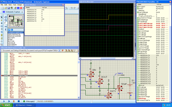
I am having a problem getting to simulate spam on f28027. If I provide an TBPRD value of 1500, when I simulate I only get a maximum value of 220. values are getting clipped @255. Also the ADC result register is getting clipped @255. for a 1.65 volt input at ADC pin, ADC Result only shows  255. whereas it should be 2048

Don't have clue why it is only 8 bit?

Will be grateful to receive some advice.

Regards

  • Hi,

    Yes, maximum value ie for 3V it should be 4096. Can you share your code esp. your ADC configuration and fetching your result register? Also, I would like you to try the sample ADC and PWM peograms present in controlSuite.

    Do keep us informed.

    Regards,

    Gautam

  • Thanks for quick reply. I am using DP library template for 2802x and getting guide from dp library user guide in control suite to write my code to generate SPWM.

    thanks

    //----------------------------------------------------------------------------------
    //	FILE:			Main.C
    //
    //	Description:	The project aims to develop a pure sine wave inverter
    //					using TI TMS320F28027 32-bit real time controller.
    //					Software block provided by TI is used as API to develop
    //					application program for the inverter.  
    //
    //	Version: 		1.0
    //
    //  Target:  		TMS320F28027(PiccoloA), TMS320F280270
    //
    //----------------------------------------------------------------------------------
    //  Copyright Khaled Smart Technologies © 20013-2014
    //----------------------------------------------------------------------------------
    //  Revision History:
    //----------------------------------------------------------------------------------
    //	Version		Date			| Description / Status
    //----------------------------------------------------------------------------------
    //	V1.0		March 2014		  Started writing final code
    //----------------------------------------------------------------------------------
    //
    // PLEASE READ - Useful notes about this Project
    
    // Although this project is made up of several files, the most important ones are:
    //	 "Main.C"	- this file
    //		- Application Initialization, Peripheral config,
    //		- Application management
    //		- Slower background code loops and Task scheduling
    //	 "DevInit_F28xxx.C
    //		- Device Initialization, e.g. Clock, PLL, WD, GPIO mapping
    //		- Peripheral clock enables
    //		- DevInit file will differ per each F28xxx device series, e.g. F280x, F2833x,
    //	 "DPL-ISR.asm
    //		- Assembly level library Macros and any cycle critical functions are found here
    //	 "Settings.h"
    //		- Global defines (settings) project selections are found here
    //		- This file is referenced by both C and ASM files.
    //
    // Code is made up of sections, e.g. "FUNCTION PROTOTYPES", "VARIABLE DECLARATIONS" ,..etc
    //	each section has FRAMEWORK and USER areas.
    //  FRAMEWORK areas provide useful ready made "infrastructure" code which for the most part
    //	does not need modification, e.g. Task scheduling, ISR call, GUI interface support,...etc
    //  USER areas have functional example code which can be modified by USER to fit their appl.
    //
    // Code can be compiled with various build options (Incremental Builds IBx), these
    //  options are selected in file "Settings.h".  Note: "Rebuild All" compile
    //  tool bar button must be used if this file is modified.
    //----------------------------------------------------------------------------------
    //IQMathLib
    #include "IQmathLib.h"
    
    //Project specific header file
    #include "Settings.h"
    
    // Include files for device support, F2802x in this case
    #include "PeripheralHeaderIncludes.h"
    #include "DSP2802x_EPWM_defines.h"		
    
    //DPLib		
    #include "DPlib.h"
    
    //Sgen Lib
    #include "sgen.h"
    
    // Driver Lib
    #include "PWM_1phInv_unipolar.h"
    
    // Solar Lib
    #include "SineAnalyzer_diff.h"
    
    
    //%%%%%%%%%%%%%%%%%%%%%%%%%%%%%%%%%%%%%%%%%%%%%%%%%%%%%%%%%%%%%%%%%%%%%%%%%%%%%%%%%%
    // FUNCTION PROTOTYPES
    //%%%%%%%%%%%%%%%%%%%%%%%%%%%%%%%%%%%%%%%%%%%%%%%%%%%%%%%%%%%%%%%%%%%%%%%%%%%%%%%%%%
    // Add protoypes of functions being used in the project here 
    void DeviceInit(void);
    #ifdef FLASH		
    	void InitFlash();
    #endif
    void MemCopy();
    
    #ifdef FLASH		//Move the InvISR from Flash to Ram if application is running from flash
    #pragma CODE_SECTION(InvISR,"ramfuncs");
    #endif
    
    interrupt void InvISR(void);		//Inverter ISR prototype declaration
    
    //-------------------------------- DPLIB --------------------------------------------
    void ADC_SOC_CNF(int ChSel[], int Trigsel[], int ACQPS[], int IntChSel, int mode);
    
    // -------------------------------- FRAMEWORK --------------------------------------
    // State Machine function prototypes
    //----------------------------------------------------------------------------------
    // Alpha states
    void A0(void);	//state A0
    void B0(void);	//state B0
    void C0(void);	//state C0
    
    // A branch states
    void A1(void);	//state A1
    void A2(void);	//state A2
    void A3(void);	//state A3
    void A4(void);	//state A4
    
    // B branch states
    void B1(void);	//state B1
    void B2(void);	//state B2
    void B3(void);	//state B3
    void B4(void);	//state B4
    
    // C branch states
    void C1(void);	//state C1
    void C2(void);	//state C2
    void C3(void);	//state C3
    void C4(void);	//state C4
    
    // Variable declarations
    void (*Alpha_State_Ptr)(void);	// Base States pointer
    void (*A_Task_Ptr)(void);		// State pointer A branch
    void (*B_Task_Ptr)(void);		// State pointer B branch
    void (*C_Task_Ptr)(void);		// State pointer C branch
    //----------------------------------------------------------------------------------
    
    //%%%%%%%%%%%%%%%%%%%%%%%%%%%%%%%%%%%%%%%%%%%%%%%%%%%%%%%%%%%%%%%%%%%%%%%%%%%%%%%%%%
    // VARIABLE DECLARATIONS - GENERAL
    //%%%%%%%%%%%%%%%%%%%%%%%%%%%%%%%%%%%%%%%%%%%%%%%%%%%%%%%%%%%%%%%%%%%%%%%%%%%%%%%%%%
    
    // -------------------------------- FRAMEWORK --------------------------------------
    
    int16	VTimer0[4];					// Virtual Timers slaved off CPU Timer 0
    int16	VTimer1[4];					// Virtual Timers slaved off CPU Timer 1
    int16	VTimer2[4];					// Virtual Timers slaved off CPU Timer 2
    
    // Used for running BackGround in flash, and ISR in RAM
    extern Uint16 *RamfuncsLoadStart, *RamfuncsLoadEnd, *RamfuncsRunStart;
    // Used for copying CLA code from load location to RUN location 
    extern Uint16 Cla1funcsLoadStart, Cla1funcsLoadEnd, Cla1funcsRunStart;
    
    // Used for ADC Configuration 
    int 	ChSel[16] =   {0,0,0,0,0,0,0,0,0,0,0,0,0,0,0,0};
    int		TrigSel[16] = {0,0,0,0,0,0,0,0,0,0,0,0,0,0,0,0};
    int     ACQPS[16] =   {8,8,8,8,8,8,8,8,8,8,8,8,8,8,8,8};
    
    // Used to indirectly access all EPWM modules
    volatile struct EPWM_REGS *ePWM[] = 
     				  { &EPwm1Regs,			//intentional: (ePWM[0] not used)
    				  	&EPwm1Regs,
    					&EPwm2Regs,
    					&EPwm3Regs,
    					&EPwm4Regs,
    				  };
    
    // Used to indirectly access all Comparator modules
    volatile struct COMP_REGS *Comp[] = 
     				  { &Comp1Regs,			//intentional: (Comp[0] not used)
    					&Comp1Regs,				  
    					&Comp2Regs,
    				  };
    // ---------------------------------- USER -----------------------------------------
    // ---------------------------- DPLIB Net Pointers ---------------------------------
    // Declare net pointers that are used to connect the DP Lib Macros  here 
    
    //ADCDRV_1ch instance #1 for AC Mains Sense
    extern volatile long *ADCDRV_1ch_Rlt1;
    
    //ADCDRV_1ch instance #2 for Inverter Voltage FB
    extern volatile long *ADCDRV_1ch_Rlt2;
    
    //ADCDRV_4ch
    extern volatile long *ADCDRV_4ch_RltPtrA;
    extern volatile long *ADCDRV_4ch_RltPtrB;
    extern volatile long *ADCDRV_4ch_RltPtrC;
    extern volatile long *ADCDRV_4ch_RltPtrD;
    
    // ---------------------------- DPLIB Variables ---------------------------------
    // Declare the net variables being used by the DP Lib Macro here 
    volatile long ACMainsV;		//For AC mains sense in the ADCINA6
    volatile long InvOutV;		//For inverter voltage feedback, ADCINB4
    volatile long BOut;			//Charging current
    volatile long BIn;			//Discharging current
    volatile long Vntc;			//NTC Thermistor temperature
    volatile long BatV;			//Battery volatge
    
    //--------------------------------- SINE GEN LIB ------------------------------------
    SGENHP_1 sgen = SGENHP_1_DEFAULTS;
    
    //-----------------------------Inverter Variables ----------------------------------
    _iq15 InvSine = 0;
    //%%%%%%%%%%%%%%%%%%%%%%%%%%%%%%%%%%%%%%%%%%%%%%%%%%%%%%%%%%%%%%%%%%%%%%%%%%%%%%%%%%
    // VARIABLE DECLARATIONS - CCS WatchWindow / GUI support
    //%%%%%%%%%%%%%%%%%%%%%%%%%%%%%%%%%%%%%%%%%%%%%%%%%%%%%%%%%%%%%%%%%%%%%%%%%%%%%%%%%%
    
    // -------------------------------- FRAMEWORK --------------------------------------
    
    //GUI support variables
    // sets a limit on the amount of external GUI controls - increase as necessary
    /*int16 	*varSetTxtList[16];					//16 textbox controlled variables
    int16 	*varSetBtnList[16];					//16 button controlled variables
    int16 	*varSetSldrList[16];				//16 slider controlled variables
    int16 	*varGetList[16];					//16 variables sendable to GUI
    int16 	*arrayGetList[16];					//16 arrays sendable to GUI*/
    
    // ---------------------------------- USER -----------------------------------------
    
    // Monitor ("Get")						// Display as:
    
    // Configure ("Set")
    
    // History arrays are used for Running Average calculation (boxcar filter)
    // Used for CCS display and GUI only, not part of control loop processing
    
    //Scaling Constants (values found via spreadsheet; exact value calibrated per board)
    
    // Variables for background support only (no need to access)
    
    
    //%%%%%%%%%%%%%%%%%%%%%%%%%%%%%%%%%%%%%%%%%%%%%%%%%%%%%%%%%%%%%%%%%%%%%%%%%%%%%%%%%%
    // MAIN CODE - starts here
    //%%%%%%%%%%%%%%%%%%%%%%%%%%%%%%%%%%%%%%%%%%%%%%%%%%%%%%%%%%%%%%%%%%%%%%%%%%%%%%%%%%
    void main(void)
    {
    //=================================================================================
    //	INITIALISATION - General
    //=================================================================================
    
    	// The DeviceInit() configures the clocks and pin mux registers 
    	// The function is declared in DevInit_F2803/2x.c,
    	// Please ensure/edit that all the desired components pin muxes 
    	// are configured properly that clocks for the peripherals used
    	// are enabled, for example the individual PWM clock must be enabled 
    	// along with the Time Base Clock 
    
    	DeviceInit();	// Device Life support & GPIO
    
    //-------------------------------- FRAMEWORK --------------------------------------
    
    // Only used if running from FLASH
    // Note that the variable FLASH is defined by the compiler with -d FLASH
    
    #ifdef FLASH		
    // Copy time critical code and Flash setup code to RAM
    // The  RamfuncsLoadStart, RamfuncsLoadEnd, and RamfuncsRunStart
    // symbols are created by the linker. Refer to the linker files.
    
    	MemCopy(&RamfuncsLoadStart, &RamfuncsLoadEnd, &RamfuncsRunStart);
    
    // Call Flash Initialization to setup flash waitstates
    // This function must reside in RAM
    
    	InitFlash();	// Call the flash wrapper init function
    
    #endif //(FLASH)
    
    
    // Timing sync for background loops
    // Timer period definitions found in PeripheralHeaderIncludes.h
    
    	CpuTimer0Regs.PRD.all =  mSec1;		// A tasks
    	CpuTimer1Regs.PRD.all =  mSec10;	// B tasks
    	CpuTimer2Regs.PRD.all =  mSec100;	// C tasks
    
    // Tasks State-machine init
    
    	Alpha_State_Ptr = &A0;
    	A_Task_Ptr = &A1;
    	B_Task_Ptr = &B1;
    	C_Task_Ptr = &C1;
    
    	VTimer0[0] = 0;	
    	VTimer1[0] = 0;
    	VTimer2[0] = 0;
    
    // ---------------------------------- USER -----------------------------------------
    //  put common initialization/variable definitions here
    
    
    //===============================================================================
    //	INITIALISATION - GUI connections
    //=================================================================================
    // Use this section only if you plan to "Instrument" your application using the 
    // Microsoft C# freeware GUI Template provided by TI
    
    //==================================================================================
    //	INCREMENTAL BUILD OPTIONS - NOTE: selected via Settings.h
    //==================================================================================
    // ---------------------------------- USER -----------------------------------------
    
    //----------------------------------------------------------------------
    //#if (INCR_BUILD == 1) 	// Open Loop Two Phase Interleaved PFC PWM Driver
    //----------------------------------------------------------------------
    	
    	// Configure PWM1&2  for 20Khz in updown count mode (Period Count= 60Mhz/(2*20Khz) = 1500)
    	//PWM_1phInv_unipolar_CNF(1,200,18,18);
    	EALLOW;																									\
    	/* 	---------------------- Init EPWM n ------------------------------------------------ */				\
    	EPwm1Regs.TBPRD 		   			= 250;     		/* Set timer period */							\
    	EPwm1Regs.TBCTL.bit.CTRMODE   		= TB_COUNT_UPDOWN;	/* Symmetric wave*/								\
    	EPwm1Regs.TBCTL.bit.PHSEN     		= TB_DISABLE;      	/* Disable phase loading*/						\
    	EPwm1Regs.TBCTL.bit.HSPCLKDIV 		= 0;          		/* Clock ratio to SYSCLKOUT*/					\
    	EPwm1Regs.TBCTL.bit.CLKDIV    		= 0;				/* SYSCLKOUT / 1*/								\
    	EPwm1Regs.TBCTL.bit.SYNCOSEL  		= TB_CTR_ZERO;		/* Sync with Sync in signal*/					\
    	EPwm1Regs.TBCTL.bit.PRDLD 			= TB_SHADOW;		/* Shadow load for PRD*/						\
    	/* Setup shadowing*/																					\
    	EPwm1Regs.CMPCTL.bit.SHDWAMODE 		= CC_SHADOW;		/* Shadow Mode*/								\
    	EPwm1Regs.CMPCTL.bit.SHDWBMODE 		= CC_SHADOW;		/* Shadow Mode*/								\
    	EPwm1Regs.CMPCTL.bit.LOADAMODE 		= CC_CTR_PRD;  	/* Load A on Zero*/								\
    	EPwm1Regs.CMPCTL.bit.LOADBMODE 		= CC_CTR_PRD; 		/* Load B on Zero*/								\
    	/* Set Actions */																						\
    	EPwm1Regs.AQCTLA.bit.CAD 			= 2;															\
    	EPwm1Regs.AQCTLA.bit.CAU			= 1;															\
    	EPwm1Regs.AQCTLA.bit.ZRO 			= 0;														\
    	/* Set Dead Band*/																						\
    	EPwm1Regs.DBCTL.bit.OUT_MODE 		= DB_FULL_ENABLE;	/* Rising Delay on 1A & Falling Delay on 1B*/	\
    	EPwm1Regs.DBCTL.bit.POLSEL 			= DB_ACTV_HIC;		/* Active Hi complementary mode (EPWMxA is inverted)*/	\
    	EPwm1Regs.DBCTL.bit.IN_MODE 		= DBA_ALL; 			/* 2A for Rising Falling */						\
    	EPwm1Regs.DBRED 					= 18;	/* Delay at Rising edge*/						\
    	EPwm1Regs.DBFED 					= 18;	/* Delay at Falling edge*/						\
    	/* 	---------------------- End Init EPWM n --------------------------------------------*/				\
    	/* 	---------------------- Init EPWM n+1 ----------------------------------------------*/				\
    	EPwm2Regs.TBPRD 		   			= 250;     		/* Set timer period */							\
    	EPwm2Regs.TBCTL.bit.CTRMODE  		= TB_COUNT_UPDOWN;	/* Symmetric wave*/								\
    	EPwm2Regs.TBCTL.bit.PHSEN    		= TB_ENABLE;      	/* Disable phase loading*/						\
    	EPwm2Regs.TBCTL.bit.PHSDIR			= TB_UP;
    	EPwm2Regs.TBPHS.half.TBPHS			= 250;
    	EPwm2Regs.TBCTL.bit.HSPCLKDIV 		= 0;          		/* Clock ratio to SYSCLKOUT*/					\
    	EPwm2Regs.TBCTL.bit.CLKDIV    		= 0;				/* SYSCLKOUT / 1*/								\
    	EPwm2Regs.TBCTL.bit.SYNCOSEL		= TB_SYNC_IN;		/* Sync with Sync in signal*/					\
    	EPwm2Regs.TBCTL.bit.PRDLD 			= TB_SHADOW;		/* Shadow load for PRD*/						\
    	/* Setup shadowing*/																					\
    	EPwm2Regs.CMPCTL.bit.SHDWAMODE 		= CC_SHADOW;		/* Shadow Mode*/								\
    	EPwm2Regs.CMPCTL.bit.SHDWBMODE 		= CC_SHADOW;		/* Shadow Mode*/								\
    	EPwm2Regs.CMPCTL.bit.LOADAMODE 		= CC_CTR_ZERO;      /* Load A on PRD*/								\
    	EPwm2Regs.CMPCTL.bit.LOADBMODE 		= CC_CTR_ZERO; 		/* Load B on Zero*/								\
    	/* Set Actions */																						\
    	EPwm2Regs.AQCTLA.bit.CAD 			= 2;															\
    	EPwm2Regs.AQCTLA.bit.CAU			= 1;															\
    	EPwm2Regs.AQCTLA.bit.ZRO 			= 0;														\
    	/* Set Dead Band for PWM1*/																				\
    	EPwm2Regs.DBCTL.bit.OUT_MODE 		= DB_FULL_ENABLE;	/* Rising Delay on 1A & Falling Delay on 1B*/	\
    	EPwm2Regs.DBCTL.bit.POLSEL 			= DB_ACTV_HIC;		/* Active high complementary mode (EPWMxA is inverted)*/	\
    	EPwm2Regs.DBCTL.bit.IN_MODE 		= DBA_ALL; 			/* 1A for Rising& Falling*/						\
    	EPwm2Regs.DBRED 					= 18;	/* Delay at Rising edge*/						\
    	EPwm2Regs.DBFED 					= 18;	/* Delay at Falling edge*/						\
    	/* 	---------------------- End Init EPWM n+1 ----------------------------------------*/					\
    	/* Clear TB counter*/																					\
    	EPwm1Regs.TBCTR            		= 0x0;         		/* Clear counter*/								\
    	EPwm2Regs.TBCTR            		= 0x0;         		/* Clear counter*/								\
    	/* ADC SOC for Inverter Control*/														   				\
    	EPwm1Regs.ETSEL.bit.SOCAEN	= 1;						/* Enable SOC on A group*/						\
    	EPwm1Regs.ETSEL.bit.SOCASEL	= ET_CTR_ZERO ;			/* Select SOC from counter at ctr = 0*/			\
    	EPwm1Regs.ETPS.bit.SOCAPRD 	= ET_1ST;				/* Generate pulse on 1st even*/					\
    	EPwm2Regs.ETSEL.bit.SOCAEN	= 1;					/* Enable SOC on A group*/						\
    	EPwm2Regs.ETSEL.bit.SOCASEL	= ET_CTR_ZERO ;	/* Select SOC from counter at ctr = 0*/					\
    	EPwm2Regs.ETPS.bit.SOCAPRD 	= ET_1ST;			/* Generate pulse on 1st event*/					\
    	SysCtrlRegs.PCLKCR0.bit.TBCLKSYNC = 1;																	\
    	EDIS;
    	// Configure ADC to be triggered from EPWM1 Period event 
       	//Map channel to ADC Pin
       	ChSel[0]=10;		//B2
       	ChSel[1]=6;			//A6
       	ChSel[2]=12;		//B4
       	ChSel[3]=4;			//A4
       	ChSel[4]=2;			//A2
       	ChSel[5]=10;		//B2
       	ChSel[6]=14;		//B6
       	/*ChSel[7]=n;		//An
       	ChSel[8]=n;			//An
       	ChSel[9]=n;			//An
       	ChSel[10]=n;		//An
       	ChSel[11]=n;		//An
       	ChSel[12]=n;		//An
       	ChSel[13]=n;		//An
       	ChSel[14]=n;		//An
       	ChSel[15]=n;		//An
       	*/
       	
       	// Select Trigger Event for ADC conversion 
       	TrigSel[0]= ADCTRIG_EPWM1_SOCA;
       	TrigSel[1]= ADCTRIG_EPWM1_SOCA;
       	TrigSel[2]= ADCTRIG_EPWM1_SOCA;
       	TrigSel[3]= ADCTRIG_EPWM1_SOCA;
       	TrigSel[4]= ADCTRIG_EPWM1_SOCA;
       	TrigSel[5]= ADCTRIG_EPWM1_SOCA;
       	TrigSel[6]= ADCTRIG_EPWM1_SOCA;
       	/*TrigSel[7]= ADCTRIG_EPWMn_SOCA;
       	TrigSel[8]= ADCTRIG_EPWMn_SOCA;
       	TrigSel[9]= ADCTRIG_EPWMn_SOCA;
       	TrigSel[10]= ADCTRIG_EPWMn_SOCA;
       	TrigSel[11]= ADCTRIG_EPWMn_SOCA;
       	TrigSel[12]= ADCTRIG_EPWMn_SOCA;
       	TrigSel[13]= ADCTRIG_EPWMn_SOCA;
       	TrigSel[14]= ADCTRIG_EPWMn_SOCA;
       	TrigSel[15]= ADCTRIG_EPWMn_SOCA;*/
       	
       	//ADC interrupt after EOC of channel 6
    	ADC_SOC_CNF(ChSel,TrigSel,ACQPS,6,0); 
       	
       	// Configure ADC SOC trigger.
    	
    	//ADC SOC is already configured by PWM_1phInv_unipolar
    	
    	// Implement phase synchronization to avoid ADC and ISR conflicts
    	/*EALLOW;
    	EPwm1Regs.TBCTL.bit.PHSEN   = TB_DISABLE;
    	EPwm1Regs.CMPCTL.bit.LOADAMODE 	= CC_CTR_PRD;
    	
    	EPwm2Regs.TBCTL.bit.SYNCOSEL = TB_SYNC_IN;
    	EPwm2Regs.TBCTL.bit.PHSDIR = TB_UP;
    	EPwm2Regs.TBPHS.half.TBPHS = 200;
    	EPwm2Regs.CMPCTL.bit.LOADAMODE 	= CC_CTR_PRD;
    	EDIS;*/
    	
    	// Digital Power CLA(DP) library initialisation 
    	DPL_Init();
    	
    	// Lib Module connection to "nets" 
    	//----------------------------------------
    	// ADCDRV_1ch block connections to DPLib net variables
    	ADCDRV_1ch_Rlt1=&ACMainsV;
    	ADCDRV_1ch_Rlt2=&InvOutV;
    	
    	// ADCDRV_4ch block connections to DPLib net variables
    	ADCDRV_4ch_RltPtrA=&BOut;
    	ADCDRV_4ch_RltPtrB=&BIn;
    	ADCDRV_4ch_RltPtrC=&Vntc;
    	ADCDRV_4ch_RltPtrD=&BatV;
    	
    	// Initialize the net variables
    	
    	ACMainsV=_IQ24(0.0);
    	InvOutV=_IQ24(0.0);
    	BOut=_IQ24(0.0);
    	BIn=_IQ24(0.0);
    	Vntc=_IQ24(0.0);
    	BatV=_IQ24(0.0);
    	
    	/* Signal Generator module initialisation           */ 
    	sgen.offset=0;
        sgen.gain=0xFA;       /* gain=1 in Q15                              */
    	sgen.freq=0x14F8CF92; 		/* freq = (Required Freq/Max Freq)*2^31 */
    								/* = (50/305.17)*2^31 = 0x14f8cf92 */
    	sgen.step_max=0x3E7FB26;	/* Max Freq= (step_max * sampling freq)/2^32 */
    								/* =(0x3E7FB26*20k)/2^32 = 305.17 */
    	
    //#endif // (INCR_BUILD == 1)
    
    //====================================================================================
    // INTERRUPTS & ISR INITIALIZATION (best to run this section after other initialization)
    //====================================================================================
    
    // Set up C28x Interrupt
    
    //Also Set the appropriate # define's in the Settings.h 
    //to enable interrupt management in the ISR
    	EALLOW;
        PieVectTable.ADCINT1 = &InvISR;		// Inverter Control Interrupt (20Khz)
    	PieVectTable.EPWM1_INT = &DPL_ISR;      // DP Lib interrupt for CNTL2P_2Z Inverter and charger control
    	
       	PieCtrlRegs.PIEIER1.bit.INTx1 	= 1;		// Enable ADCINT1 in PIE group 1
       	PieCtrlRegs.PIEIER3.bit.INTx1	= 1;		//Enable EPWM_1INT in PIE group 3
       	
       	EPwm1Regs.ETSEL.bit.INTSEL = ET_CTR_PRD;  	// INT on PRD event
       	EPwm1Regs.ETSEL.bit.INTEN = 1;              // Enable INT
        EPwm1Regs.ETPS.bit.INTPRD = ET_1ST;         // Generate INT on event
       	//
    
        IER |= M_INT1;                          	// Enable CPU INT1 for ADCINT1,ADCINT2,ADCINT9,TripZone
        IER |= M_INT3;                          	// Enable CPU INT3 connected to EPWM1-6 INTs:
        EINT;                                   	// Enable Global interrupt INTM
        ERTM;                                   	// Enable Global realtime interrupt DBGM
    	EDIS;      
    
    //=================================================================================
    //	BACKGROUND (BG) LOOP
    //=================================================================================
    
    //--------------------------------- FRAMEWORK -------------------------------------
    	for(;;)  //infinite loop
    	{
    		// State machine entry & exit point
    		//===========================================================
    		(*Alpha_State_Ptr)();	// jump to an Alpha state (A0,B0,...)
    		//===========================================================


    	}
    } //END MAIN CODE


    //=================================================================================
    //	STATE-MACHINE SEQUENCING AND SYNCRONIZATION
    //=================================================================================
    
    //--------------------------------- FRAMEWORK -------------------------------------
    void A0(void)
    {
    	// loop rate synchronizer for A-tasks
    	if(CpuTimer0Regs.TCR.bit.TIF == 1)
    	{
    		CpuTimer0Regs.TCR.bit.TIF = 1;	// clear flag
    
    		//-----------------------------------------------------------
    		(*A_Task_Ptr)();		// jump to an A Task (A1,A2,A3,...)
    		//-----------------------------------------------------------
    
    		VTimer0[0]++;			// virtual timer 0, instance 0 (spare)
    	}
    
    	//Alpha_State_Ptr = &B0;		// Comment out to allow only A tasks
    }
    
    void B0(void)
    {
    	// loop rate synchronizer for B-tasks
    	if(CpuTimer1Regs.TCR.bit.TIF == 1)
    	{
    		CpuTimer1Regs.TCR.bit.TIF = 1;				// clear flag
    
    		//-----------------------------------------------------------
    		(*B_Task_Ptr)();		// jump to a B Task (B1,B2,B3,...)
    		//-----------------------------------------------------------
    		VTimer1[0]++;			// virtual timer 1, instance 0 (spare)
    	}
    
    	Alpha_State_Ptr = &C0;		// Allow C state tasks
    }
    
    void C0(void)
    {
    	// loop rate synchronizer for C-tasks
    	if(CpuTimer2Regs.TCR.bit.TIF == 1)
    	{
    		CpuTimer2Regs.TCR.bit.TIF = 1;				// clear flag
    
    		//-----------------------------------------------------------
    		(*C_Task_Ptr)();		// jump to a C Task (C1,C2,C3,...)
    		//-----------------------------------------------------------
    		VTimer2[0]++;			//virtual timer 2, instance 0 (spare)
    	}
    
    	Alpha_State_Ptr = &A0;	// Back to State A0
    }
    
    
    //=================================================================================
    //	A - TASKS
    //=================================================================================
    //--------------------------------------------------------
    void A1(void) 
    //--------------------------------------------------------
    {
    	
    	//-------------------
    	//the next time CpuTimer0 'counter' reaches Period value go to A2
    	A_Task_Ptr = &A2;
    	//-------------------
    }
    
    //-----------------------------------------------------------------
    void A2(void) 
    //-----------------------------------------------------------------
    {	 
    	//-------------------
    	//the next time CpuTimer0 'counter' reaches Period value go to A1
    	A_Task_Ptr = &A3;
    	//-------------------
    }
    
    //-----------------------------------------
    void A3(void)	
    //-----------------------------------------
    {
    	
    	//-----------------
    	//the next time CpuTimer0 'counter' reaches Period value go to A1
    	A_Task_Ptr = &A4;
    	//-----------------
    }
    
    
    //----------------------------------------------------------
    void A4(void) 
    //---------------------------------------------------------
    {
    	//-----------------
    	//the next time CpuTimer0 'counter' reaches Period value go to A1
    	A_Task_Ptr = &A1;
    	//-----------------
    }
    
    
    //=================================================================================
    //	B - TASKS
    //=================================================================================
    
    //----------------------------------- USER ----------------------------------------
    
    //----------------------------------------
    void B1(void)
    //----------------------------------------
    {		
    	//-----------------
    	//the next time CpuTimer1 'counter' reaches Period value go to B2
    	B_Task_Ptr = &B2;	
    	//-----------------
    }
    
    //----------------------------------------
    void B2(void) // Blink LED on the control CArd
    //----------------------------------------
    {
    	//-----------------
    	//the next time CpuTimer1 'counter' reaches Period value go to B3
    	B_Task_Ptr = &B3;
    	//-----------------
    }
    
    //----------------------------------------
    void B3(void)  
    //----------------------------------------
    {
    	//-----------------
    	//the next time CpuTimer1 'counter' reaches Period value go to B4
    	B_Task_Ptr = &B4;	
    	//-----------------
    }
    
    //----------------------------------------
    void B4(void) //  SPARE
    //----------------------------------------
    {
    	//-----------------
    	//the next time CpuTimer1 'counter' reaches Period value go to B1
    	B_Task_Ptr = &B1;	
    	//-----------------
    }
    
    
    //=================================================================================
    //	C - TASKS
    //=================================================================================
    
    //--------------------------------- USER ------------------------------------------
    
    //------------------------------------------------------
    void C1(void) 	 
    //------------------------------------------------------
    {
    	//-----------------
    	//the next time CpuTimer2 'counter' reaches Period value go to C2
    	C_Task_Ptr = &C2;	
    	//-----------------
    
    }
    
    //----------------------------------------
    void C2(void) 
    //----------------------------------------
    {
    
    	//-----------------
    	//the next time CpuTimer2 'counter' reaches Period value go to C3
    	C_Task_Ptr = &C3;	
    	//-----------------
    }
    
    
    //-----------------------------------------
    void C3(void) 
    //-----------------------------------------
    {
    	//-----------------
    	//the next time CpuTimer2 'counter' reaches Period value go to C4
    	C_Task_Ptr = &C4;	
    	//-----------------
    }
    
    
    //-----------------------------------------
    void C4(void) //  SPARE
    //-----------------------------------------
    {
    	//-----------------
    	//the next time CpuTimer2 'counter' reaches Period value go to C1
    	C_Task_Ptr = &C1;	
    	//-----------------
    }
    
    // ISR for inverter 
    interrupt void InvISR()
    {
    	
    	EINT;
    //-------------------------------------------------------------------
    // Inverter State execution
    //-------------------------------------------------------------------
    	
    	//VrmsReal = _IQ15mpy (KvInv, sine_mainsV.Vrms);
    	// frequency generation using Sine Gen function
    	sgen.calc(&sgen);
    	InvSine = sgen.out;
    	
    	//Inverter Drive
    	//PWMDRV_1phInv_unipolar(1, _IQ15(1500), _IQ24mpy((InvSine<<9), 1));
    	
    	if ( InvSine >= 0)																\
    	{																					\
    		EPwm1Regs.CMPA.half.CMPA	= 0 ;												\
    		EPwm2Regs.CMPA.half.CMPA	= ((abs(InvSine))*(0.78));			\
    	}																					\
    	else																				\
    	{																					\
    		EPwm1Regs.CMPA.half.CMPA	= ((abs(InvSine))*(0.78));	\
    		EPwm2Regs.CMPA.half.CMPA	= 0 ;												\
    	}
    	
    	//-------------------------------------------------------------------
    	//			 Reinitialize for next ADC sequence 
    	//-------------------------------------------------------------------
    	PieCtrlRegs.PIEACK.all = PIEACK_GROUP1;		// Must acknowledge the PIE group
    	AdcRegs.ADCINTFLGCLR.bit.ADCINT1 = 1;		// Clear ADCINT1 flag
    	//-------------------------------------------------------------------
    	
      	return;
    
      	
    }
    

  • Hello,

    If you put ADC result register, for example AdcResult.ADCRESULT1, into watch window, what is the result?

    Can you give the screenshot?

    Best regards,

    Maria

  • Hello, for an input voltage of 1.64982 at the ADCINB2 and corresponding SOC5, the ADCRESULT5=255.

    Which should be 2047/2048. an screenshot is given for your convenience.

    Thanls

  • Hello,

    I have never used Proteus 8 for simulating Piccolo.

    I feel like maybe there is bug on the modelling of PIccolo device in Proteus.

    Do you have any F28027 kit (for example LAUNCHXL-F28027) to try to read these ADC values using CCS?

    Also can you try this simulation using ControlSuite example for ADC (or using other simple ADC code)?

    Best regards,

    Maria

  • Hi

    Thanks for the suggestion. May be you are right.

    Unfortunately, the place I live these kits are not available locally. Since I don't have an international card, I am unable to buy right now.

    I will try your suggestion. Do you have any recommendation for simulation software?

    thanks

  • Hi,

    Do you have any recommendation for simulation software?

    Here's how you can perform simulation: http://e2e.ti.com/support/microcontrollers/c2000/f/171/t/98887.aspx

    Regards,

    Gautam