This thread has been locked.

If you have a related question, please click the "Ask a related question" button in the top right corner. The newly created question will be automatically linked to this question.

F28M36 - ePWM issue

Dear TI Team,

for the Concerto (F28M36) I need to setup an single PWM channel which is able to send out a predefined (e.g. 16)
number of pulses on request only.
After the output of these predefined number of PWM pulses, the PWM channel should stop autonomous
without using an external TZ signal or furthermore controlling.

e.g.:
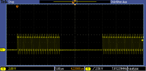
      Start of PWM pulses                     autonom PWM stop
                v                                               v
                |-|    |-|   |-|    |-|    |-|   |-|    |-|    |-|  
------------| |---| |---| |---| |---| |---| |---| |---| |--------------
            

Is there any code sample or can you give me a hint to realize it?

Thanks
WJ

  • Hi WJ,

    I can think of two potential options of doing what you want:

    (1)
    I can think of one way that should be pretty flexible and not use too much CPU bandwidth.  I'd tie your PWM output to a GPIO pin capable of eCAP functionality.  I think you'll then have the flexibility you need to generate an interrupt after n PWM periods with some combination of the below eCAP register settings:
    -the existence of up to 4 timestamps that can be triggered serially
    -the ability to generate an interrupt when any of these timestamps trigger
    -the ability to prescale (divide-down) the input

    In the generated interrupt you could then force a trip event (or you could read a flag if that is preferred). 

    (2)
    Instead of using the PWM to generate the pulses you want directly, you could use the PWM chopper submodule of the ePWM.  This may be the better option if the pulses are very high frequency.


    Thank you,
    Brett

  • Hi Brett,

    thanks for feedback.

    Your second option, I did already tested (personally I would prefer this option).
    Mainly it do work (the chopper function), however the PWM still continue (with the chopper function).
    So I tried to figure out how can I stop autonom the PWM after the first period (what is the main issue).

    Next I will check out your first option.
    I'll give you feedback asap.

    Thanks
    WJ

  • Here  is a 3rd option:

    enable ePWM-period interrupts; in ePWM-ISR count the number of interrupts; if your theshold is reached, switch ePWM off.


  • Hi Frank,

    absolutely the best way to do it.

    It needs an further ISR routine, however it is acceptable in this case.

    I am just wondering why I did not saw the "ETSEL.INTSEL" bits!


    Anyway, many thanks for your option and solution.

    Best regards
    WJ

  • Hi Frank,

    I just would like to add a note.

    A proper execution with 'Option 3' is guaranteed only as long as no higher IRQ (group or level) runs when the 'PWM ISR' is in process or it is ready to serve.

    In this case the 'PWM ISR' - is postpone and do not stop at the rigth time the PWM period.
    The result is that the PWM starts a new period.

    Good case

    :

    Bad case ('PWM ISR' - is postponed):

    Thanks again.

    Best regards
    WJ

  • Yes, that's right.

    But what you can always do in such a situation is to use nested interrupts. Example: You can program your 2nd "Not-ePWM"-Interrupt-Routine on entry in such a way that it allows the ePWM - Interrupt to interrupt it. If the ePWM-ISR is short (which is the case for just a disable instruction for the ePWM), the impact to your 2nd ist is minimal - and it will happen only once, because the ePWM is disabled afterwards. Please also note that for C28x devices nested interrupts means also that an interrupt sorece from a lower IRQ can be nested in a higer IQR - line - so there is always room to tweak in your ePWM-ISR.


  • Hi Frank,

    I added now the IRQ nesting.
    It works fine for 99.9%.

    However, the latency time to 'enable the nested IRQ' (in the higher prior ISR) may cause that the stopping of the current PWM-Chopper signal may to late and the next PWM-chopper cycle is already started.

    Anyway, Frank many thanks for your specific hint.

    It looks like that my proposed clocking (to serve an ADC) is not realizable.

    Best regards
    WJ

  • Hi Frank,

    so now I got the final solution.

    The last issue was only, because I configured the starting PWM pulse with CMPA = 1;.

    Since the latency time to 'enable the nested IRQ' was pass, the next PWM cycle (EPWMxA set to high) may already on the way.

    So I moved the compare clock 'CMPA' to activite the 'CAU: EPWMxA set to high' to a higher value (of course including the ending clock CMPB).
    Now is enough time to switch the 'nested IRQ' and stop the PWM cycle in a save time, even a new PWM cycle is started.

    Thanks for your intention with option3.

    Best regards
    WJ

  • Great, that you could also bypass that last obstacle.

    I was just trying to compose an answer to your 2nd last mail, asking about the signal shape and frequency of the signal, you found a solution.