This thread has been locked.

If you have a related question, please click the "Ask a related question" button in the top right corner. The newly created question will be automatically linked to this question.

Motor Identification is successful but doesn't spin. Identified values are strange

Other Parts Discussed in Thread: MOTORWARE, BOOSTXL-DRV8301

Good afternoon,

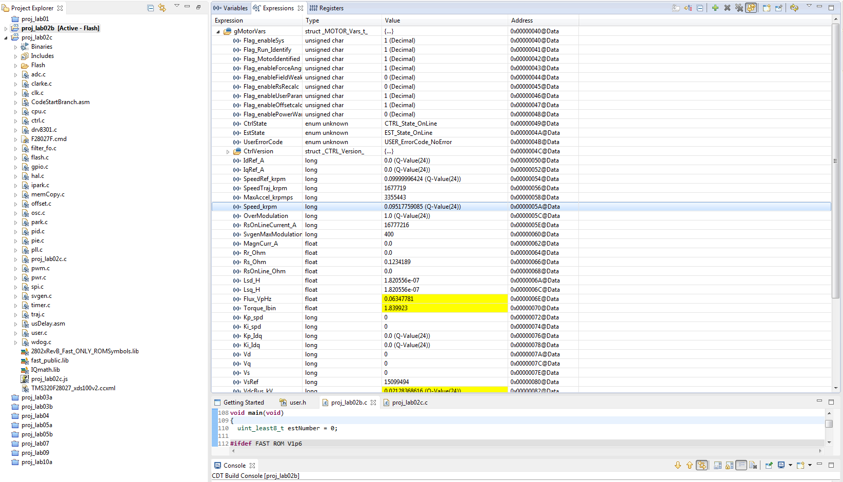
We have been trying to identify a motor for some time without success. This motor was designed with low inductance but we have not measured it independently. After much fiddling with the user.h file and the accompanying spreadsheet we finally got the identification to finish. Unfortunately the inductance values seem wrong and the motor doesn't spin neither in the identification nor current controller.

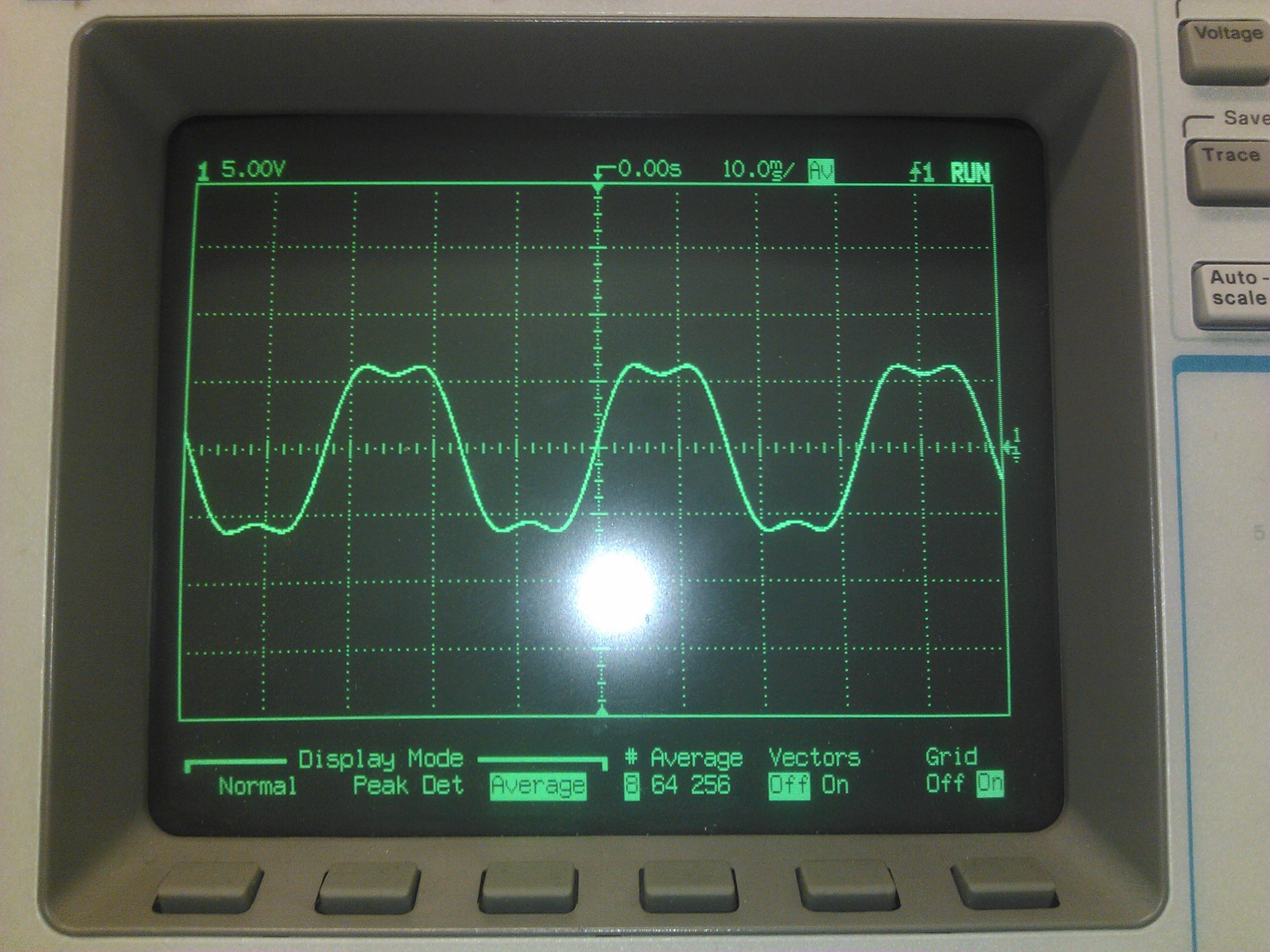
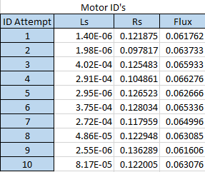
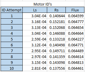
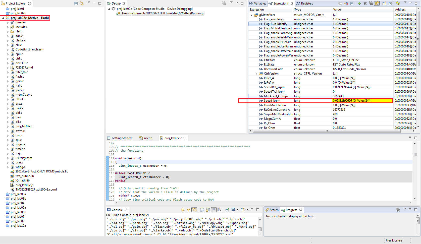
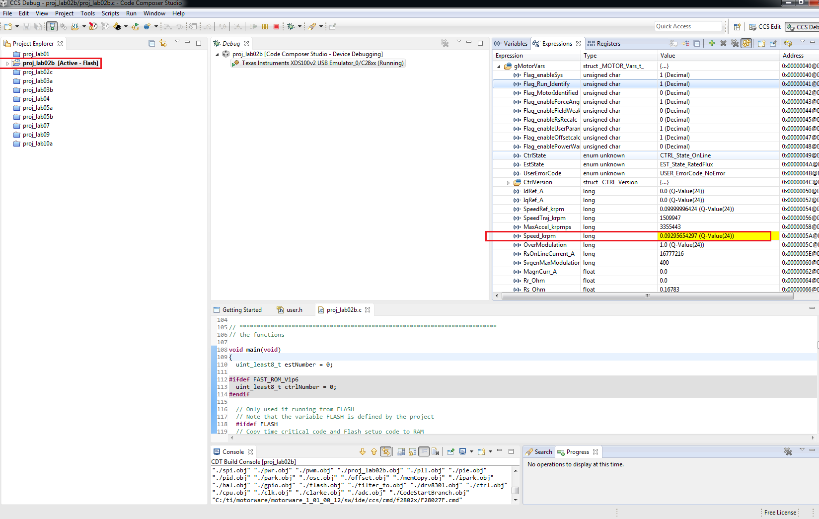
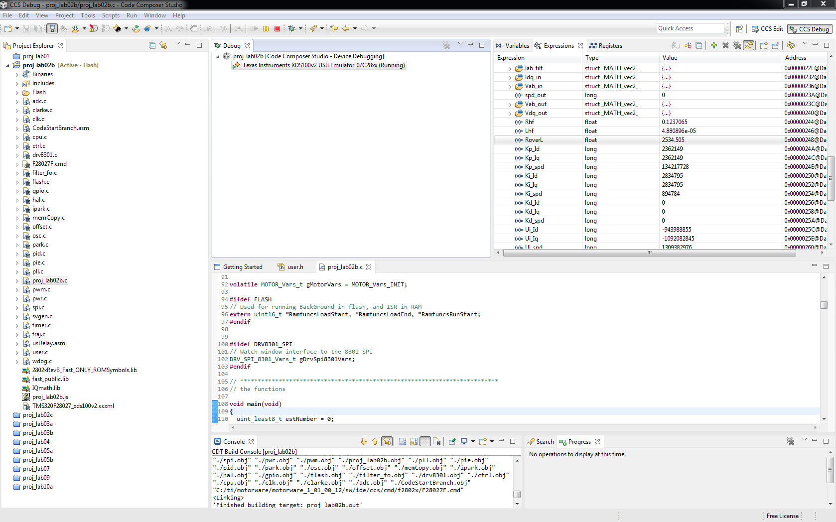
The inductance values fall within a small range spread apart several orders of magnitude. Sometimes we have 1E-9 magnitudes and others 1E-4. Either way the motor never spins when on the ramp up, with one weird exception. During the flux estimation the motor spins smoothly without any noise and as intended. During the rest of the identifications the motor acts glitchy and a bit chaotically, not spinning.

We have tried increasing the RES_EST_CURRENT and well as the USER_MOTOR_MAX_CURRENT. We don't have the load attached yet, just the motor inertia.

We have changed some of the files according to the changes in the attached excel.

2577.motorware_selecting_user_variables_gamma.xlsx

The user.h is the one attached.

2867.user.h

We also have some previous changes according to this thread, but we think it is not a problem since the place where the adc values gets plugged does not exist in project2c. We are using a lauchpadXL with the boosterXL driver.

http://e2e.ti.com/support/microcontrollers/c2000/f/902/t/329620.aspx

Some times when we are adjusting values we also get R_OVER_L invalid errors and we must scale down to 100instead of the defaults 300, which is strange.

We also get USER_ErrorCode_ctrlFreq_Hz_Low when we make some adjustments. What is this about?


Thanks

Paulo Neves

  • Hi, Paulo,

    I notice that your active motor is called "eco_shell". Are you competing in the eco shell competition?  It is coming up soon here in Houston :)

    is this a hub motor? direct drive or with an internal gear?
    What is Vbus?  Expected maximum speed (RPM or Hz)? Maximum current?

    I'm a bit surprised to see you using a BOOSTXL-DRV8301 board. This is 24V and most hub motors I've seen are 36 or 48V for increased power.

    You have 20 pole pairs selected, which means with
    #define USER_IQ_FULL_SCALE_FREQ_Hz        (101.6)
    You are claiming you will only run to 101.6 * 120 / 40 = 304.8 RPM
    I doubt this value very much.

    There is no reason to have your IQ_FULL_SCALE so low....please leave at default
    (800.0)
    for this exercise

    Please tell me why you have selected
    #define USER_IQ_FULL_SCALE_VOLTAGE_V      (12.0)

    We tell you only to lower it to this value if that is the Vbus value you are using.  It is usually a good idea to keep this to a minimum of USER_ADC_FULL_SCALE_VOLTAGE_V     /     2  = (14.0)
    And as mentioned I doubt you are actually running a 12V motor. Set this value to your Vbus as a minimum (which is also the maximum for this BOOSTXL-DRV8301)

    #define USER_ZEROSPEEDLIMIT   (1)
    This is completely incorrect and THE REASON YOUR ID IS NOT WORKING.  Let's set this to a value for 2Hz. So if you use the (800.0) frequency above, you can change this to
    #define USER_ZEROSPEEDLIMIT   (0.0025)

    let's change this to a value 2x this 2Hz we just set
    #define USER_FORCE_ANGLE_FREQ_Hz            (4.0)

    leave this to default
    #define USER_MAX_ACCEL_Hzps                 (20.0)

    this should be fine as you have a < 1 kHz motor
    #define USER_R_OVER_L_EST_FREQ_Hz (100)

    You should be able to ID very straight forward on this motor. 

  • Hi Chris,

    We are going to participate in Eco Shell, but in Roterdam :D

    We do not have yet the battery power pack for 24V so we are trying to identify the motor with only 12V battery pack still. The best value for maximum speed is the target speed of 304RPM.

    We have a hub motor indeed. We only have the nominal speed target for best efficiency of the motor, which is around 277RPM. It is pretty slow but we are looking for efficiency.

    The motor now does ramp up in the ID part. The problem is the identified values for inductance still go from 1E-12H to 1E-3 magnitudes.

    The worse is when we input our expected values in User.h we get ctrlUSER_FREQUENCY LOW

  • have you corrected all of the items in my post above?

    Again, this motor is super simple to ID, so you are simply making a mistake in how you set up the user.h.


  • Well sure hope so. The changes we have made are in this user.h in attachment. We have input the values of previous identifications and we these we cannot even get past this 2 errors:

    ctrlUSER_FREQUENCY LOW and User_ErrorCode_iqFullScaleVoltage_V_low

    7823.user.h

  • try using attached


    7823.user.h
  • Ok, we did the ID but and the results consistently show an inductance of 0.0053 Henries (the values of Ls_H are in Henries I assume)

    The problem is that as soon as we input the obtained values in the ID we get User Error Code iqFullScaleVoltage V low.

    7573.user.h

  • Good, 3.8mH makes some sense for this motor.

    Give R/L = 92 Hz, a bit lower than expected for your motor, but reasonable.  My guess is your Ls is probably a bit lower and could be found with proper Vbus, EST_FREQ, and IND_CURREN.

    Short circuit current = V/Hz / 2pi / H = 0.161 / 6.28 / 0.0038 = 6.7A, which is much less than your 10A setting. Again, I think the Ls is probably a little lower, but this motor is probably designed for more like 8A Isc and 5A continuous.

    The error you get comes from this pre-compile check in user.c

      if((USER_IQ_FULL_SCALE_VOLTAGE_V <= 0.0) ||
        (USER_IQ_FULL_SCALE_VOLTAGE_V <= (0.5 * USER_MOTOR_MAX_CURRENT * USER_MOTOR_Ls_d * USER_VOLTAGE_FILTER_POLE_rps)) ||
        (USER_IQ_FULL_SCALE_VOLTAGE_V <= (0.5 * USER_MOTOR_MAX_CURRENT * USER_MOTOR_Ls_q * USER_VOLTAGE_FILTER_POLE_rps)))
        {
       USER_setErrorCode(pUserParams, USER_ErrorCode_iqFullScaleVoltage_V_Low);
        }

    24.0 <= 0.5 * 10 * 0.0038 * 364.682 * 6.28

    24.0 <= 43.51

    Consdiering your Isc above, you should probably change

    #define USER_MOTOR_MAX_CURRENT          (5.0)

    at which point it will build and run w/o errors.

    Also, the Flux of this motor (0.161 V/Hz) suggest that at 150 Hz (450 RPM) it will produce more than 24V of Bemf.  But I beleive you plan to keep this to about 100 Hz (300 RPM) so you should be fine.


    Ok, you should be ready to go. 

    BTW - if you want a tip on winning the eco challenge....I suggest using InstaSPIN-MOTION and the st-curve.  This will save you energy on all accelerations and planned decelerations (though coasting is even better when you can of course - just turn off the inverter).


  • We fiddled with the EST_FREQ, and IND_CURRENT and no luck still.

    The values returned are not valid to drive the motor. The motor spins with lots of noise and barely.

    With our design values set in user.h the motor spins better when running lab04 but not satisfactorily.

    We also checked the waveform that was going to the motor and it was terribly noisy. Something is not good.

    We also doubt of the quality of the build of the motor, because when we check the waveform of the motor as a generator the sinusoidal is slightly clipped like below. Do you think this is a critical flaw?

    Another thing, can you refer me to the bibliography that explains the relationship between flux and short circuit current? I thought the short circuit current was calculated in a worse case scenario by simple ohm law.

  • don't "fiddle". the user.h I gave you should work just fine. The values you have in USER_MOTOR are reasonable for stable control.

    You have the right idea of using lab4 or 5a intitially. This takes the speed loop tuning out of the picture and lets you see if the FOC is working well.  A VERY good step.  With most motors the default speed loop setting in 5b is usually stable enough for some testing and hand tuning, but with very small high speed motors, or very high inertia motors (like an e-bike on a wheel) they need significant tuning.

    Make sure as you enable the motor you have either saved the Offsets in your user.h or you enable the OffsetCalc flag.

    With 12V and a Vs (duty cycle) limit of 1.0 I suspect you will get about 40 Hz = 120 RPM.

    If your motor is damaged all bets are off...Your waveforms look like a true BLDC motor (which is rare, but certainly possible).  InstaSPIN-FOC works just fine on these motors, it just drives them with sinusoidal waveforms so you lose a bit of torque efficiency.

    Isc is just one of the calculations we recommend making (and is in the Universal GUI) to do some sanity checking if the parameters make sense for what you think the motor should do.  Isc gives you a single number that takes into account flux/bemf and inductance.  Same that R/L gives you a feeling for the maximum Hz of the motor.  Very useful to check the parameters ID'd.  A higher short circuit current usually means you need to PWM faster and probably run your current controller faster.

    For an e-bike you are usually fine with 10-16 kHz PWM and even 5-8 kHz current loop, but the 45 kHz / 15 kHz defaults you are using should be fine for initial bring up.

    . .

  • Anöther thing, is it normal that even with NULL values in the offsets they, the bias arrays are always set to 0? The enableOffsetcalc is set to 1 as can be seen in the expression watch picture above

  • the bias array is a "user variable" that is only used in certain labs. It is filled by the _get functions in proj_lab##.c 

    Ex:

    gMotorVars.I_bias.value[0] = HAL_getBias(halHandle,HAL_SensorType_Current,0);

    If you want to always see the actual offset in any project, directly view the

    hal.adcBias

    structures like I use in the UNIVERSAL GUI


  • Hmm, will investigate tomorrow when i get back to the lab. In the mean time we made a video in the hope somebody can spot some problem in our setup. Thank you a lot for your help!

    https://www.youtube.com/watch?v=G3Tpmyvkkqc&feature=youtu.be

    6064.user.h

  • 1. is the motor just in the middle, or are all those wires part of an outer stator?  If the motor is just the middle portion disconnect everythign from the shaft to do ID.

    2. when you start ID please report this variable in Expressions View: ctrl.RoverL

    Does it hit 2000.0?  Does it go negative?

    3. If it goes negative try using #define USER_R_OVER_L_EST_FREQ_Hz (300.0) in your user.h  

    4. make sure you are using proj_lab02c


  • It does hit more than 2000 but it does not go negative, meaning no iq_ overflow I guess.

    The identification surely does not get accurate values. We have followed the procedures described in http://cache.freescale.com/files/microcontrollers/doc/app_note/AN4680.pdf to obtain the the Ls_q and Ls_d manually. Specifically we got 53E-6 H. Then, we have tried to set the Ls_d and q of the motor in the user.h for lab05a. Again USER_ErrorCode_ctrlFreq_Hz_Low pops up. We have commented out the part of the code that checks the error so that we can run. The motor runs and if we adjust the current coefficients we get somewhat better results in terms of error between measured current and set iqref.

    The motor is slightly smoother if I try to arrange the PI gains according to TI documentation. We have set the Ki_iq to R/L = 0.12/53.3E-6 = 2250. When I put this value, the Ki_iq just overflows, goes negative and everything stops working. Do you think that its the problem?
     The error between the iqref set and the actual measured output is quite different. Do you think it is a coefficients problem?

  • Paulo,

    use proj_lab02c to ID the motor, this is required for the low Ls motor you obvioulsy have.

    You obviously have changed something else in user.h

    If your Ls is 56uH that's fine, use (0.000056).  You should not get errors if the rest of user.h is set correctly. If you get an error you can look in user.c to understand what variable might have caused this. Ex:

      if(((float_t)USER_CTRL_FREQ_Hz < USER_IQ_FULL_SCALE_FREQ_Hz) ||
        ((float_t)USER_CTRL_FREQ_Hz < USER_OFFSET_POLE_rps) ||
        ((float_t)USER_CTRL_FREQ_Hz < 250.0) ||
        ((float_t)USER_CTRL_FREQ_Hz <= (2.0 * USER_IQ_FULL_SCALE_FREQ_Hz * USER_MOTOR_MAX_CURRENT / (128.0 * USER_IQ_FULL_SCALE_CURRENT_A))))
        {
          USER_setErrorCode(pUserParams, USER_ErrorCode_ctrlFreq_Hz_Low);
        }

      if((USER_MOTOR_Rs != 0.0) && (USER_MOTOR_Ls_d != 0.0) && (USER_MOTOR_Ls_q != 0.0))
        {
          if(((float_t)USER_CTRL_FREQ_Hz <= (USER_MOTOR_Rs / (USER_MOTOR_Ls_d + 1e-9))) ||
            ((float_t)USER_CTRL_FREQ_Hz <= (USER_MOTOR_Rs / (USER_MOTOR_Ls_q + 1e-9))))
            {
             USER_setErrorCode(pUserParams, USER_ErrorCode_ctrlFreq_Hz_Low);
            }
        }


    You do NOT need to change the current controller gains. They will work absolutely fine as calculated with valid parameters and valid user.h

    use proj_lab02c to ID and run using proj_lab05a for torque mode.

    No need to go beyond those labs at this point.


    Please post your latest user.h


  • We managed to find our big problem by now. We're using version 5.5 of CSS without noticing all the compatibility problems.

    After installing version 6 we got a successful Motor ID and the sound of motor running seems now really smother and healthy.

    We got some more questions:

    1. The torque value is floating from negative ranges to something around 20.  Can you help us debugging this particular variable?

    2. Can we get feedback of the AC current and voltage passing through the phases?

    3. Is it normal to expect current decreasing while applying some load on the motor?

    Thank you in advance

  • My guess is you never updated your compiler to 6.2.3+ in CCSv5.5.  Moving to CCSv6 had compiler 6.2.5 default which is probably what solved your problems.

    I've actually never used CCSv6....guess I should give it a try :)


    1. In MotorWare _12 the gMotorVars.Torque_lbin value should be valid when you view in the Expressions menu, but it is NOT updated every control cycle (not that the real-time could keep up with it)

    There is a documented bug inside the library for the getTorque function, so it has to be calculated manually with other variables.  This calculation takes too many cycles inside the ISR, so it is in the background task.   In any of the .c projects you can find this function

      // get the torque estimate
      gMotorVars.Torque_lbin = calcTorque_lbin(handle);

    and review the calculation for calcTorque_lbin()  (also for nM)

     If you are using the UNIVERSAL GUI I've noted there is an incorrect scaling of the variable on the PC side.  I've fixed the update I'm working on. If you want to try to fix yourself, inside CCS GUI Composer edit the GUI, click on the Torque widget, right click the little ... where my mouse is, and remove any formatting.


    2.  you are sampling all your values every cycle and keeping them in pAdcData, so you can do what you like with them. 

    3. Iq and Is will increase as you load the motor, up to any limit you've set  (in speed control mode the Iq Reference will be limited to USER_MAX_MOTOR_CURRENt).

    Decreasing current under load would be a bad sign...I would suspect the angle estimation was significantly off, potentially due to bad feedback (too low of speed).

  • You were right about the compiler. Good lord, how long we took to figure that out.


    We added a way to watch the iq and id currents used in the torque calculation and they vary wildly, being the culprit for the crazy torque readings we have. Do you think this may be related to the wrong angle estimate? If so, do you think we should try to increase the flux of the motor?


    Another thing, the unloaded current of the motor is terribly high for the extremely low the friction of our system. Again, do you think this is related to the low flux of the motor (0.07)VpHz?


    Thanks for everything

  • attach your user.h so I can see if I see anything strange.

    you are running proj_lab05a and leaving the current gains as default, correct?


    Paulo Neves said:
    If so, do you think we should try to increase the flux of the motor?

    How do you propose to do that? Are you designing your own motors?  If you did increase the flux with a new design, you would get more torque and less short circuit current (lower current ripple).

    0.07 isn't low unto itself.....twice as much as the standard NEMA17 24V/4A motor we ship.


    Paulo Neves said:
    Another thing, the unloaded current of the motor is terribly high for the extremely low the friction of our system. Again, do you think this is related to the low flux of the motor (0.07)VpHz?

    All of these things sound like the current controllers are not tuned or the PWM isn't keeping up with the control. Let me look at your user.h


  • Atached follows our User.h

    5722.user.h

  • These are the values in your user.h

    Is this what you identified most recently with the compiler fix?

    #define USER_MOTOR_Rs                   (0.091654896)
    #define USER_MOTOR_Ls_d                 (0.000240255)
    #define USER_MOTOR_Ls_q                 (0.000240255)
    #define USER_MOTOR_RATED_FLUX           (0.057014614)

    Just doing some checking on your values

    Rs / Ls = 379 Hz

    Isc = 37..8 A

    These both seem reasonable for this motor....I would have expected Ls to be a bit smaller perhaps to give a higher R/L.

    Your Ls isn't so low that I would think it needs higher PWM than the 30 KHz you are using, and the 10 KHz control and estimator are just fine.

    I made a few changes.  Let's try to ID again with proj_lab02b first.

    please report

    ctrl.RoverL
    Rs
    Ls
    Flux

    and insure that it starts spinning at RampUp, reaches a speed of 90 RPM, and continues spinning until RampDown and Motor Identified.

    After you post these results you can try proj_lab02c....but it should be needed to IDthis motor, 02b should work just fine.


  • Thanks for the assistance,

    The values we reported in the previous(but after compiler fix) user.h are an average. In attachment we send an image with the various identifications we made. The identification results are not always consistent.

    We are designing our own motor, so we can influence the flux.

    One interesting thing is that the speed does not get to 90RPM during the ID, instead it stays aruond 50RPM.

    We will report on the results with the new user.h you sent.

  • This is with proj_lab02b and the user.h I attached? 

    What is the ctrl.RoverL value? I've asked you to confirm several things in my above post, please do so.


    This is really strange...the Rs valus should be much more stable than this.
    Please lower this to the minimum value that still allows the motor to start spinning during RampUp phase of motor ID:
    USER_MOTOR_RES_EST_CURRENT      (3.0)
    I would suspect that (1.0) should still allow the motor to start-up.

    Flux value is good and in a correct range.

    The Ls value is very unstable...especially for somethign in the hundreds of uH it should be much more consistent.

    Paulo Neves said:

    One interesting thing is that the speed does not get to 90RPM during the ID, instead it stays aruond 50RPM.

    That's not good. It must reach for valid values:

    USER_MOTOR_FLUX_EST_FREQ_Hz     (30.0)

    With 20 pole pairs that's 90 RPM.

    Is gMotorVars.SpeedRef_krpm showing 90 RPM during the Flux ID state:  (0.08999 in the watch window)  ?

    Screenshots please.


  • The image with table we sent before was not done withyour user.h, but the results are similar to your new user.h

    The result of the identification with the user.h you attached in proj02b is below.

    As you can see the inductance identification is not always consistent and other times(like the image below) just invalid. On the other hand the RPMs now follow the reference RPM closely.

    The RoverlL is 2781.303.

    Below is a print screen of the speed on ramp up. Now the speed is correct. We have tried to lower the USER_MOTOR_RES_EST_CURRENT but then the motor doesnt ramp up during the STATE_RAMP_UP, only during the flux estimation. Should we keep trying to get a smaller current until it doesnt ramp up?

    Do you think it would be easier for us set up a teamsview session with webcam for you to do the identification yourself?

  • Pedro Alves said:

    The RoverlL is 2781.303.

    when you see this >= 2000 with proj_lab02b you need to instead try proj_lab02c

    Please run 2c now.

    Pedro Alves said:
    On the other hand the RPMs now follow the reference RPM closely.

    Low speed is dominated by Rs, so the 0.12 ohm seems pretty accurate.

    Your Ls is invalid (hence the need to use 02c), but at low speed and low load having essentially 0 Ls set still allows FAST to preform ok since Rs dominates the motor model.

    Pedro Alves said:
    Below is a print screen of the speed on ramp up. Now the speed is correct.

    This didn't show up.  So 90 RPM is set and reached during Motor ID?

    Pedro Alves said:
    Should we keep trying to get a smaller current until it doesnt ramp up?

    I would use the smallest possible current... if 2.0 works, use that instead of 3.0

    Pedro Alves said:

    Do you think it would be easier for us set up a teamsview session with webcam for you to do the identification yourself?

    Not sure if that will help at this point....buy maybe soon. What timezone are you in?

  • After another 10 consecutive ID's with your User.h and proj_lab02b we got the attached results.

    The magnitudes are more consistent by now.


    As you noticed before our motor generates a trapezoidal wave-form as generator. Will we get better results with:

    #define USER_MAX_VS_MAG_PU        (4.0/3.0)  ? Whats the main difference?

  • That's MUCH better....I still think you should run some with 2c though. Having the RoverL go > 2000 in 2b is an issue that 2c should solve.

    How does this run?

    Pedro Alves said:

    As you noticed before our motor generates a trapezoidal wave-form as generator. Will we get better results with:

    #define USER_MAX_VS_MAG_PU        (4.0/3.0)  ? Whats the main difference?

    You can NOT use this setting unless you use the files in proj_lab10 where over modulation is explained. A different SVGEN module is required and some different sampling schemes.  However, you will still use sinewave modulation up to a value of Vs = 1.0 before the new modulation kicks in to increase your effective voltage you can apply to the motor up to Vs = 1.333 (4/3).

    Leave it at 1.0 in the user.h. Only update to 1.333 if you are using the files from proj_lab10 (in fact, I would always leave user.h as 1.0 and just hardcode in the variable update in lab10, that way if you use Motor ID in system you don't get this problem (it seems this was effecting your ID).


    You lose some efficiency if your modulation doesn't match your Bemf. So for your trapezoidal motor you do lose a bit of efficiency....but you usally gain it back by the better efficiency of FOC at variable speeds and dynamic loads.

    If you are designing your motor I'd use sinusoidal windings for efficiency.

    You go get a slightly higher initial torque out of trap windings, but it's not worth it IMO for this application.


  • This last post with the tables was run with lab02b...apparently the inductance values are much more consistent as you can see from this 2nd table. The expected inductance of the whole coil and motor system is now actually close to the values of lab02b.

    On the other hand with the lab02c, inductance is mostly invalid as you saw in the first table. Lab02c is mostly not working for us, the motor runs very roughly and the reference RPMs are not reached.

    Continuing to monitor the RoverL we noticed that there were inconsistencies also. It varies quite significantly but always above 2000.

    About the 4/3, wow, that was a mistake. Sorry about that.

    The screenshots were forgotten, We send the printscreens in attachment. 

    With the USER_MOTOR_RES_EST_CURRENT lower we get it to spin up but it stops then the state changes from State_RampUP to State_RatedFlux.

    We are in UTC time so it is still just 21.00 here :)

    The lab02c

    The lab2b:

    With the values of lab02b the lab04 runs much smoother and efficiently by the way.

  • Paulo Neves said:

    Continuing to monitor the RoverL we noticed that there were inconsistencies also. It varies quite significantly but always above 2000.

    Please confirm: with proj_lab02b the ctrl.RoverL during Motor ID is > 2000?  If so, that's surprising...I need to think about why that woudl happen and why it still works.  What is ctrl.Rhf and ctrl.Lhf?

    Paulo Neves said:
    ith the USER_MOTOR_RES_EST_CURRENT lower we get it to spin up but it stops then the state changes from State_RampUP to State_RatedFlux

    That's the expected behavior, per SPRUHJ1 User's Guide after RampUp it moves to RatedFlux.

    Since the motor spins and reaches the Frequency target for RatedFlux at this lower RES_EST_CURRENT please continue to use the lower value and see if your Rs value gets more stable.

    I had you change USER_R_OVER_L_EST_FREQ_Hz from (300) default for the BOOSTXL to (100)....your motor isn't high frequency enough to use (300)...I think this may have been throwing your Rs readings (the next state after RoverL).  You should have stable Rs ID now.


    Everything for you is solved now, correct? 

    BTW - I installed CCSv6 and everything I've run in MotorWare is working just fine.


  • ChrisClearman said:
    Please confirm: with proj_lab02b the ctrl.RoverL during Motor ID is > 2000?

    Yes, it is. Here the screenshots on lab02b and lab02c:

    ChrisClearman said:
    Everything for you is solved now, correct? 

    We got better behaviour by now but the unloaded motor still requires more power than the expected. The unloaded power required shoud be around 0.5W(measured mechanical losses) and we are measuring on the dc bus 10W. This 10W@300RPM was obtained with some iteration on the current PI coefficients. Slightly better yet, the current does rise when we apply load. We seem to be getting better response increasing the Kp slightly but then the motor starts hissing and loses control if we increase further.  Unfortunately the guide to calculate the current gains does not give us sensible gains.

  • Pedro Alves said:
    The unloaded power required shoud be around 0.5W

    Why do you think it should be 0.5W?

    With 24V that means 0.02A.

    I find that completely unbelievable for this motor.

    Pedro Alves said:
    yet, the current does rise when we apply load.

    Ummm, of course it does!  You apply load, the motor uses current, and the FOC allows just enough for the torque you are commanding.


  • We actually got really good efficiency out of the board and motor once we tuned the PI gains. We are around 70% with the controller, motor and windings set.

    The problem now is that we are already at the competition and we barely can start up with load. We are trying different settings of force angle frequency. The 4.0Hz frequency you previously suggested does not work with the load on.

    We have decreased the frequency to 0.5 and strangely, we get more success with the usb cable connected than with the controller standing alone. We find this really weird and cannot actually make up an explanation for this. When we have the controller standing alone do we just take out the JP1 or, do we have to take out all the jumpers(JP1, JP2 JP3)?

    What parameters would you suggest tuning, and in what direction? With high current references the wheel vibrates a lot, heating up the board. Below the violent reference current threshold mentioned, the motor swings more or less softly. The frequency of the swing varies with the force angle frequency but so far, the values we tried seem to almost work but never do.

    We just have a LaunchXL and BoostXL boards so we only have instaspinFoc and not spintac. Out of desperation we have already connected and integrated the hall sensors in part of our code, but have not quite discovered where would we add a simple EST_setAngle_pu in our adapted lab05 code.

  • Paulo,

    We know of start-up issues on e-bike type applications. There are many ways to solve. The best knowing the angle before you start-up, which is what we are working on (with great success) and will release later.

    With what you have now, I assume you are using a speed controller?  When you look at the output of the speed PI controller do you see it increasing and saturating at a maximum value, as if it was continuing to command maximum torque?  What can happen is that the speed feedback becomes corrupted so the input reference to the Iq torque controller doesn't actually ask for maximum torque.  That's why I recommend starting in Torque mode (in fact, most e-bikes are run in Torque mode all the time, but I understand for your competition you may have to set constant speeds and let the bike move itself).

    As for the ForceAngle, I think in your case it will be more trouble than it's worth.  You should probably disable and just start driving the motor. With most e-bike motors just barely moving it (even if it's just the rider giving it a gentle push forward with their toes) will allow FAST to completely lock on and you can drive to a higher torque / speed.

    Paulo Neves said:
    once we tuned the PI gains.

    Just curious, do you mean the speed gains, or did you also tune the current controller gains?  The current controller gains are tuned numerically and are usually quite good.


  • No we were meaning current loop gains.

  • how much did you change them from default?  This may be one issue, that you have either made them to stiff or too soft for the high dynamics that are required for start-up.  I would use the default current gains.


  • We will tell you the difference in 5 minutes. Meanwhile what about the other questions, like the hall sensors for startup?

  • If you can get a valid angle from the halls, you can EDT_setAngle

    And then startup, it will help on the angle certainly. 

    Not sure how close you are to having the halls working....if this is new to you I'd probably focus my time on the other methods I mentioned. 

  • and what about:

    Paulo Neves said:

    we get more success with the usb cable connected than with the controller standing alone. We find this really weird and cannot actually make up an explanation for this. When we have the controller standing alone do we just take out the JP1 or, do we have to take out all the jumpers(JP1, JP2 JP3)?

    Thanks in advance

  • That's pretty strange.

    this is the settings for the boot switches on the LaunchPad.  Default is 1 1 1 for development.

    JP1, 2, and 3 should stay removed as power is being provided by the inverter power and you want to keep isolation to the FTDI  USB JTAG.