This thread has been locked.

If you have a related question, please click the "Ask a related question" button in the top right corner. The newly created question will be automatically linked to this question.

Instaspin gui problem.

Other Parts Discussed in Thread: DRV8301, BOOSTXL-DRV8301, LAUNCHXL-F28027F, MOTORWARE

Hi everyone.

I'm working with DRV8301 kit and TMS320F28069MPZT control board. I can turn the many different motor with using instaspin gui composer v1. But I can not get the same performance from the motor using the lab.

I'm writing in program (lab 2a, 3a, 5c) all the parameters contained in the GUI.

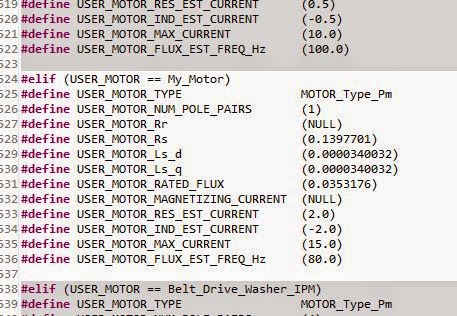
As seen in the picture below very stable motor is turning at 3000 rpm.

However, after 5000 rpm and the motor gets so hot you can not control the speed. Also I write 6000-7000, and 8000 can not change the rpm.

What is the reason?

Best regards.

  • 1. that's a very small Ls value. Did you use proj_lab2c to ID these motor params?

    2. after 2c work through lab3s to understand how to save your offsets and motor varlues, then move to 5a and run in torque mode. This removes the speed loop which may be causing you an issue. 

    3. recall that the speed loop is not tuned automatically. especially with these small high speed motors the speed PI gains are too aggressive and you will get oscillations, especially at higher speeds.  tune at 0 speed and then step response, or use InstaSPIN-MOTION in lab5c-5e to help you tune with a single parameter (it is much easier and much better performance).

    4. you didn't post your user.h, but I assume you are using defaults at PWMing at at least 45 KHz. That will be required for this motor.

    5. Is this a hobby motor, like a helicopter? These type of outrunners are not built to run for very long w/o the air cooling provided by the blades.  They will overheat....but you should still be able to regulate speed for some time, especially at high speeds where the Ls value is much more important than the Rs value (which will be increasing as you heat the motor).


  • Hi Chris.

    We tried all the suggestions above, you have wrote. But there were no changes. We do not use hobby motor. We used the motor parameters are as follows.

    1) Rated Voltage : DC 14.4V
    2) Load Current : 1.5A
    3) No_Load Speed : 135000rpm
    4) Max.efficiency point, Torque : 80mN.m
    5) Max.efficiency point, Speed : 11600rpm
    6) Max.efficiency point, Current : 9.3A
    7) Stall Current : 61A
    8) Stall Torque : 0.59 Nm

    I add below the data we obtained with GUI. According to these data user.h could you prepare it?

    Thank you in advance for your help.

  • Don't use the standard GUI, it won't work for your motor.

    You are going to have to make some HW changes to use this motor.

    1. Your maximum voltage is 15V and you are trying to use an EVM scaled for over 66V. So you are using only the bottom 1/4 of the resolution.  You will never ID properly with this EVM and motor combination.  The best EVM to use would be the BOOSTXL-DRV8301 24V/10A.  Even with this, I would suggest updating all the voltage scaling on the inverter to measure about 0-16V.  But, you should be able to at least ID first with this inverter.

    2. You have set a max freq of 225 Hz....um no, you missed a decimal place.  You want to run at 2250 Hz, extremely high speed.  You will have to update your user.h appropriately for FULL_SCALE_FREQ, but note that there is a maximum limite for FULL_SCALE_FREQ that is 4 * the FILTER POLE.  That is ok, just use the maximum value allowed.

    3. You will need to PWM very quickly (at least 45 KHz) and you will likely need to run your current controller at lease at 20 KHz (since you need to run at 2KHz+ speeds)....this is going to be tough to do on the LAUNCHXL-F28027F (or any 2x device due to low MIPS) so you will probably have to use the F28069M controlCARD you have).  So I would change your voltage HW on the DRV8301 EVM to measure 16-18V or so and just use your 69M controlCARD with 60 KHz PWM and /3 TICKS to get your control loop to 20 KHz.

    This is a tough one...it will be very challenging to get everything set correctly.

    What sort of application is this for?

  • Hi Chris.

    I'll try the changes you suggested. 

    I understand what you say but do not have a problem with the GUI. DRV8301 using the card of 200 to 13,500 rpm motor can rotate in a very stable manner.

    I do not understand these issues, why can not adapt these parameters to the program? Why the motor does not work properly with the labs (2a,3b or 5c)?

    Best regards.

  • Ahmet BURMA said:
    with the GUI. DRV8301 using the card of 200 to 13,500 rpm motor can rotate in a very stable manner.

    What do you mean?  You use InstaSPIN-FOC or -MOTION GUI to ID the motor and it works well from 200-13,500?

    1. Accordiing to your motor specs, 13,500 RPM would only be 10% of rated speed....so I don't think it's working like you think it is.

    2. In your GUI screen shot you have the max frequency set at 225 Hz.   This is only 13,500  RPM for a 1 pole pair motor.  You say it runs to 135,000 RPM per spec.

    3. I'm frankly shocked that you were able to ID the Ls of this motor to 34uH using DRV8301 EVM and 15V bus.  That usually won't work....but this gives you an Rs/Ls = 4 kHz, which is typical for this type of motor, and an Isc = 165A, which is a bit high for a 9A motor, but typical of how these high speed motors are designed. 

    I can't promise that these value are valid....it's very rare that the standard GUI will ID a motor like this correctly...but they seem pretty reasonable and where I would expect.

    Ahmet BURMA said:
    I do not understand these issues, why can not adapt these parameters to the program?

    There are two different issues being discussed.

    1. Is a matter of ADC resolution.  You are only looking at maximums of 15V and yet all the ADC scaling for the DRV8301 EVM is based on 66.32V, so you are using only the lower 20% of available range. This is not a good design for this motor.  Then there is the matter of the "per unit" resolution inside of the software, and how this range effects the smallest Resistance, Flux, and inductance we can measure.  Simply, you need to set-up the HW and then the SW to maximize resolution and put variables into the correct range.  This is because the same software algorithms are being used on these tiny little hobby motors up to Mega Watt motors.  You can't expect the software to "just work" on any motor with any hardware scaling at any time.

    2. The matter of motor ID.  The motor ID process that is in ROM on the devices does NOT work for all motors. It is meant to work with "standard motors".  As soon as we released InstaSPIN-FOC we realized how many "non-standard" motors people were trying to use it for: super high speed / low inductance; ultra-high torque; custom induction motors, etc.  To make the motor ID process work for these "non-standard" motors we have added some state logic to the projects that put variables into a different range/resolution or re-set PI control gains to handle these types of motors.

    proj_lab2c = high Rs / Ls, or low flux, or low Ls, or low Vbus motors (e.g. high speed hobby motors, transportation motors, medical drills/tools)

    proj_lab2a-d = updates for Induction motor ID. 

    With the proper HW/SW scaling pretty much every 3-ph motor can now be properly ID'd and controlled. The ones that we still haven't solved are special low voltage induction motors.  We will eventually update the projects to ID these as well.


  • Hi Chris.

    I videotaped our application .

    http://tinypic.com/r/syax35/8

    But the need to explain a few things.

    1. Video of 200 RPM - 5200 RPM - 13,000 RPM are taking place for the trial .

    2. I do not show for the 13,000 rpm tachometer is problematic . For this reason, I will try to explain cycles using body         contact . The black plastic in tachometer reader 's probe diameter 14.1mm is . Motor shaft diameter is 6mm . Read       the 5540 rpm tachometer with body contact that we , the actual transfer must use the following formula to calculate .

        Actual speed = ( tachometer diameter / motor shaft diameter) * on-screen reading .

        Actual speed = ( 14.1mm / 6mm ) * 5540

        Actual speed = 2.35 * 5540

        Actual speed = 13,019 RPM

    I hope I could tell you exactly what I mean .

    I am also sending User.h file . Maybe you'd like to examine .

    Using Lab absolutely can not get up from 6,200 rpm .

    I still have not been able to solve the problem .I tried changing all variables in user.h. ( ex. USER_NUM_PWM_TICKS_PER_ISR_TICK or USER_NUM_ISR_TICKS_PER_CTRL_TICK or USER_NUM_CTRL_TICKS_PER_CURRENT_TICK )

    I only do not changes the hardware variables.

    #define I_A_offset (0.9939797521)
    #define I_B_offset (1.014363647)
    #define I_C_offset (1.005615234)

    #define V_A_offset (0.5020679235)
    #define V_B_offset (0.4977650046)
    #define V_C_offset (0.4986107945)

    Perhaps our problem is this; GUI and labs is using different hardware parameters.if so, it uses the hardware parameters of the GUI Is there any way of learning?

    I'm very glad if you help.

    Best regards.

    4150.user.h

  • Ahmet,

    I know English isn't your first language, so I appreciate the challenges in discussing.

    You aren't taking my advice that I've suggested.

    1. your user.h is still using 225 Hz max, which for 1 pole pair motor = 13,500 RPM

    #define USER_IQ_FULL_SCALE_FREQ_Hz        (225.0)

    Please follow the spreadsheet I have recommended to update this to the maximum allowed for your hardware (4.0 * USER_VOLTAGE_FILTER_POLE_Hz)

     2.  again, follow the spreadsheet to lower you voltage to the bus voltage

    #define USER_IQ_FULL_SCALE_VOLTAGE_V      (15.0)

    At the same time, read my posts above about the limitation, and how you likely need to re-scale both your voltage and current sensing to enhance resolution.

    3. user.h decimation

    follow the spreadsheet

    4. use proj_lab2c to ID the motor, then save those values before trying to run proj_lab5a for torque mode (take the speed loop tuning out of the equation).


  • Hi Chris;

    We solve problems. cause of the problem compiler version. motor  turning smoothly. We will be more than a question.

    We want you to connect any input button. How do we do in the program push-button control. In this way we make not;

    hall.c :

    GPIO_setMode(obj->gpioHandle,GPIO_Number_16,GPIO_16_Mode_GeneralPurpose);
    GPIO_setLow(obj->gpioHandle,GPIO_Number_16);
    GPIO_setDirection(obj->gpioHandle,GPIO_Number_16,GPIO_Direction_Input);

    main.c :

    GPIO_Handle gpioHandle;

    StartButton=GPIO_read(gpioHandle,(GPIO_Number_e)GPIO_Number_16);

    if (Start_Button){

          MotorStartPr(true);

    }

  • Hello,

    I use this HAL_getGpioData() in main.c Also I enable pull-up for the GPIO.

    Hope this helps you.

    Best regards,

    Maria

  • hello maria,

    Where this procedure?I could not find.

    Thank you.

  • Oh, yes, I forgot that I made it by myself to make it easier calling GPIO APIs in main :)

    This is the code:

    static inline uint16_t HAL_getGpioData(HAL_Handle handle,const GPIO_Number_e gpioNumber)
    {
      HAL_Obj *obj = (HAL_Obj *)handle;

      return GPIO_getData(obj->gpioHandle,gpioNumber);
    }

    I put it in hal.h

    Best regards,

    Maria

  • GPIO_getData(obj->gpioHandle,gpioNumber); ??

  • Aha, you are using F28069F/M. I use F28027F (the APIs are more complete) and you can follow the same for F28069F/M, please see gpio.c from F28027F and copy it to F28069F/M gpio.c.

    C:\ti\motorware\motorware_1_01_00_12\sw\drivers\gpio\src\32b\f28x\f2802x

    Best regards,

    Maria

  • But I think you can use GPIO_read() (mentioned in gpio.c of F28069F/M) to replace GPIO_getData().