This thread has been locked.

If you have a related question, please click the "Ask a related question" button in the top right corner. The newly created question will be automatically linked to this question.

Lab2a low inductance estimated

Other Parts Discussed in Thread: MOTORWARE, DRV8312, LAUNCHXL-F28027F, BOOSTXL-DRV8301, DRV8301

Hi,

I have been trying to run a small motor with these values listed on the spec:

R= 0.5 ohm

L = 170 uH

rated speed = 24 krpm

24 V with 2.8 A max current.

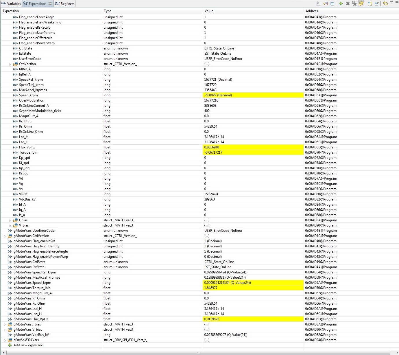
When I run lab02a or b I get these results (See screenshot) with very low inductance estimated. The motor tracks the ref speed only for positive speeds and stalls for negative ones. I have tried different things (starting with NULL or the spec values but had no luck).

Here is My_Motor setting

#elif (USER_MOTOR == My_Motor)
#define USER_MOTOR_TYPE MOTOR_Type_Pm
#define USER_MOTOR_NUM_POLE_PAIRS (7)
#define USER_MOTOR_Rr (NULL)
#define USER_MOTOR_Rs (0.5)
#define USER_MOTOR_Ls_d (.000068)
#define USER_MOTOR_Ls_q (.000068)
#define USER_MOTOR_RATED_FLUX (0.03955824)
#define USER_MOTOR_MAGNETIZING_CURRENT (NULL)
#define USER_MOTOR_RES_EST_CURRENT (0.2)
#define USER_MOTOR_IND_EST_CURRENT (-0.2)
#define USER_MOTOR_MAX_CURRENT (2.0)
#define USER_MOTOR_FLUX_EST_FREQ_Hz (80)

Any help is highly appreciated. 

Thanks,

Sina
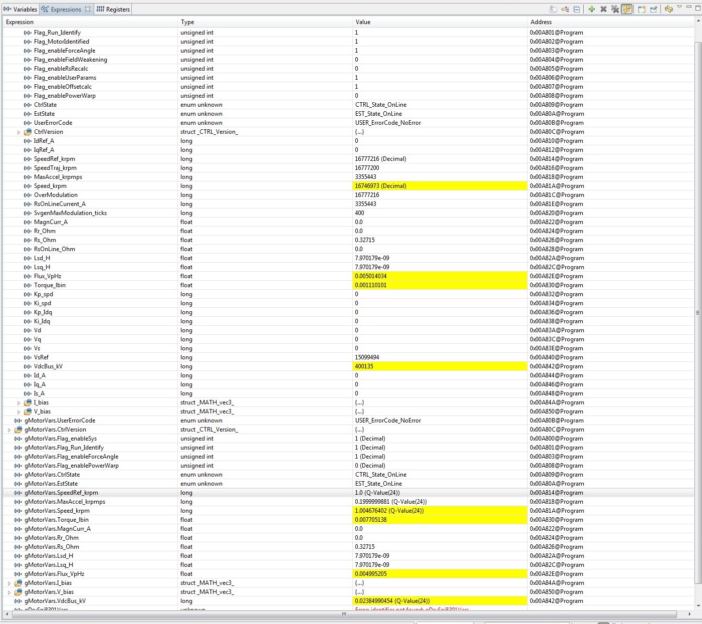
 

  • if you look at ctrl.RoverL (with F2802x) or controller* --> RoverL (F2806x) you will see that your RoverL has saturated to 2000.0

    You need to use proj_lab2c to ID high RoverL (high speed) motors.

    You should also follow the sticky post "setting your user.h" and the spreadsheet included.


  • Thanks Chris,

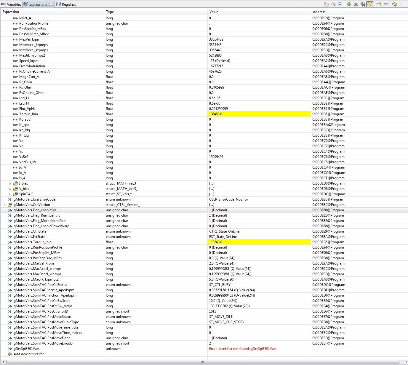
    I followed the sticky note on user.h (see my user.h attached) and now I am getting values that are way off and no spinning. I have also attached the specs of the motor that I am trying to control. the following files are attached:

    excel sheet, user.h, screenshot of code composer and motor specs. Any thoughts?

    Thanks,

    Sina

    6013.motorware_selecting_user_variables_v2p0.xlsx

    0310.user.h

  • I'm on mobile so can't view the files, but your Rs has a gross error of 56 kohm.

    Are are your phase wires hooked up? Seems like an open.

  • I realized the error in Rs. That is a side effect of changing the values based on the excel sheet. In fact if I run from the InstaSpin Gui with default values it runs the same way as before. Can you please take a look at my user.h whenever you can and let me know what is wrong?


    btw, the screenshot is from running lab02c. Is there a way to type in the values that are know (R, L , inertia) and skip this step? I am interested in doing accurate position control on this motor (with encoder input) but I am stuck on lab02.

    Sina

  • from the user.h it looks like you are using DRV8312-69M-KIT, is that correct?

    you ported over the lab2c project? (it isn't included in MotorWare _12 for DRV8312)


    1. What is the flux value in your first post. Just a guess or calculated?

    #define USER_MOTOR_RATED_FLUX (0.03955824)

    If I work backwards from the max torque, max current, and your 7 polepairs, I should have a Flux in V/Hz of 0.0213

    2. Are you sure this has 7 pole pairs?  That drives a very high frequency of 2800 Hz for 24 KRPM....If pole pairs is lower, Max Freq is lower, and flux is lower. Most high speed motors are only 1 or 2 pairs.

    3. If I calculate out the Rs / Ls, it is just over 2800 Hz. Typically these motors are designed higher than the actual Hz, so I doubt this motor can reach 2800 Hz....

    4. If I calcualte the short circuit current I get almost 40A.  That's very high for such a low current motor.  That means that although this motor only draws 2.8A continous, it will have much higher switching peaks.  I am guessing that the DRV8312 is actually clippping the output.  You probably need to use another driver.  The BOOSTXL-DRV8301 would work well for this motor...however, IF this this actually a 2800 Hz motor the LAUNCHXL-F28027F (that we have to pair with the BOOST today) is not a good fit, as it can NOT run the PWM, current loop, and estimator as high as required.  These very high speed motors take A LOT of MIPS because you have to close the control and  estimator loops at lease 8 * faster than the speed you are running (from control theory).


    This combination of poles, flux, and Ls just doesn't seem right...it's very unusual, especially from what I think is a pretty small motor, correct?


    5. Does the 0.2A of current start the motor during ID stage RampUp?   And does the rotor spin the entire time until RampDown and Motor Identified?  It needs to be high enough to do so.

    here is the updated parameters that I would use (our Rs and Ls is line to neurtral, not line to line from your motor datasheet)

    #elif (USER_MOTOR == My_Motor)
    #define USER_MOTOR_TYPE                 MOTOR_Type_Pm
    #define USER_MOTOR_NUM_POLE_PAIRS       (7)
    #define USER_MOTOR_Rr                    (NULL)
    #define USER_MOTOR_Rs                    (0.25)//(0.5)
    #define USER_MOTOR_Ls_d                  (0.000087)
    #define USER_MOTOR_Ls_q                  (0.000087)
    #define USER_MOTOR_RATED_FLUX           (0.0215)
    #define USER_MOTOR_MAGNETIZING_CURRENT  (NULL)
    #define USER_MOTOR_RES_EST_CURRENT      (0.2)
    #define USER_MOTOR_IND_EST_CURRENT      (-0.2)
    #define USER_MOTOR_MAX_CURRENT          (2.8)
    #define USER_MOTOR_FLUX_EST_FREQ_Hz     (150.0)


    I'm still very surprised / worried about the Rs value.

    Can you double check the toggles on the DRV8312 board?  It is easy to bump one of them, and the results will be very strange values. The toggles need to be in the middle.


    Hopefully you can help clarify some of above and we can get you pointed in the right direction.  But if this is a 2800 Hz motor it's going to be very challenging to do this with a 60-90 MHz MCU.


  • wait, I miscalculated with the wrong torque value from the table.

    for 0.024 Nm; Flux V/Hz = 2pi *0.024 / 1.5 / polepairs / 2.8A = 0.005 V/Hz (with 7 polepairs)

    that gives Isc = Flux V/Hz / 2pi / Ls = 9A, which is much more realistic.


    Can you verify the 7 pole pairs?


  • I am Using the  DRV8312-69M-KIT. You are right, lab02c does not exist for this kit. I had imported the wrong project (8301 kit) instead. Is it possible to run the low inductance motor with DRV8312? If so what is the procedure? 

    1.The flux value was not calculated. I will use the 0.005 V/Hz that you calculated.

    2. The motor is definitely 7 pole pair permanent magnet. 

    I have had the motor spinning with 0.2A starting current and it kept spinning during the entire ID process. Although that is really dependent on other parameters defined in user.h. 

    Given the motor parameters at hand and based on your calculations is it feasible to control this motor with DRV8312 and InstaSpin Motion? As I mentioned earlier I am interested in accurate position control with the encoder input (vs sensorless speed control). 

    Thanks Again,

    Sina

  • 0. It is possible, but these motors usually have high switching currents that the drv8312 clips so it doesn't turn out so well. But your motor isn't that bad, if may work. I would normally attach the a zip, but my laptop just died. You can copy over the proj_lab2c folder from drv8301 and use a text editor to change any instance of 8301 to 8312 in the three included files.

    If you are using an encoder the motor ID is moot. It is only used to set the starting current gains, and the values you have are close enough. 

    However, with position control are you trying to hit top speeds of 2800 Hz? That will be an issue for the encoder as well.

    I've sent to Adam from LineStream to help, but after you save your user.h values in lab3 you can move on to lab12. 

  • Sina,

    If the motor has good control with InstaSPIN-FOC there should be no issue with controlling the motor using InstaSPIN-MOTION in position control.  InstaSPIN-MOTION uses the FOC included with InstaSPIN-FOC as the underlying control scheme.  

    The sensorless velocity is a good way to get your motor functional and to tune the current regulators.  Once the motor can be controlled via this scheme, it is easy to integrate the encoder and use position control with InstaSPIN-MOTION.

  • Thanks Chris. Did I understand correctly that I can skip lab2, do lab3 and then move to lab12? What user.h parameters do you suggest? 

    lab2c--> lab3 --> lab12

    or 

    lab3-->lab12?

    Adam-- I have been having trouble with instaspin FOC and this motor possibly due to low inductance and high speed of the motor or RoverL of about 3000 or higher. The question is whether I can skip some steps since we have an encoder. Of the labs provided which ones are essential for getting sensored position control to work (with encoder without halls)? 

    I have also put an encoder on the motor provided with the kit so I can compare the results assuming that the labs work correctly with that motor.

  • sina,

    yes, I think you need to move on to lab12...it expects that you have already gone through the lab 5, but you can work through it.  lab12 is used for encoder feedback.

    for the parameters I would use


    #elif (USER_MOTOR == My_Motor)
    #define USER_MOTOR_TYPE                 MOTOR_Type_Pm
    #define USER_MOTOR_NUM_POLE_PAIRS       (7)
    #define USER_MOTOR_Rr                    (NULL)
    #define USER_MOTOR_Rs                    (0.25)//(0.5)
    #define USER_MOTOR_Ls_d                  (0.000087)
    #define USER_MOTOR_Ls_q                  (0.000087)
    #define USER_MOTOR_RATED_FLUX           (0.005)
    #define USER_MOTOR_MAGNETIZING_CURRENT  (NULL)
    #define USER_MOTOR_RES_EST_CURRENT      (0.2)
    #define USER_MOTOR_IND_EST_CURRENT      (-0.2)
    #define USER_MOTOR_MAX_CURRENT          (2.8)
    #define USER_MOTOR_FLUX_EST_FREQ_Hz     (150.0)


  • Sina,

    You should be able to go straight to lab 12.  You might need to manually adjust the current loop tuning, but it should work.  The instructions in lab 12 walk you through using an encoder to replace FAST.  

    One thing that will impact the position control is an accurate inertia estimate.  There are a couple options here.

    1. Manually adjust the inertia value to get a good response.

    2. Update lab 12 to include the inertia estimation from lab 05c.

    3. Wait until the next MotorWare, which will have a sensored inertia id lab.

    For Position Control I would run through these labs:

    Lab 12 -> Verify your encoder is functioning properly, this lab will also let you manually adjust the current loop tuning

    Lab 13a -> Tune the SpinTAC Position Controller

    Lab 13b ->Position Transitions, this lab does point to point position transitions

    These are the key labs to make your system functional.  After these labs you can run through the rest of the 13x labs in order to see some advanced functionality.

  • Thanks. After updating the user.h parameters I now get a better response with lab2a and lab3. Although lab3 only works for positive ref_speeds and for negative commands it just stops.


    Can you please confirm the encoder pin configuration on J4:

    from 1

    CH A, CH B , IND , 5V, GND ?


    in lab12 the motor does an initial kick but then stops. Is there a switch that needs to be flipped for encoder input? I read this line in the HW Guide under board features("Quad encoder interface and hall sensor interface available for speed and position measurement (only if MCU supports and SW is enabled)")

    Thanks,

    Sina

  • Sina,

    That is the correct pinout for the encoder connection on J4.  

    When you ran lab 02a which direction did the motor spin?  Typically it should spin anti-clockwise in this lab.  It is important that the motor and encoder are aligned in terms of direction.

    Did you configure your encoder in the user.h file?

    One way to verify this is to add "st_obj.vel.conv.Pos_mrev" into the watch window.  Before you set "gMotorVars.Flag_Run_Identify" to 1, manually rotate the motor in the anti-clockwise direction.  You should see the Pos_mrev increase, and when you reach one rotation it should be equal to 1.

  • The spin was clockwise then the motor stops and is resisting motion. I followed your suggestion and st_obj.vel.conv.Pos_mrev reads zero before gMotorVars.Flag_Run_Identify is set to 1 with no change on manual rotation of the shaft. After setting the flag to 1 it stays at -4096.

    Just to confirm same switch configuration as before works with encoder? Is there an electrical way of aligning the motor and encoder? If they are not aligned should I still get reasonable numbers in st_obj.vel.conv.Pos_mrev on manual rotation (or is this indicative of a problem with the encoder itself and not the alignment?)


    Thanks,

    Sina

  • Sina,

    When you ran lab 02a previously what direction did the motor spin?

    The same switch configuration will work with sensored or sensorless systems.

    The alignment between motor and encoder happens automatically, during EST_State_Rs.

    Manually rotating the motor checks that the encoder is functioning properly and is scaled correctly.  

    I forgot to mention that the Pos_mrev signal is a Q24 value

    You have continuous refresh enabled correct?  If not it can be difficult to watch the Pos_mrev signal change as you rotate the motor.

  • in lab02 it was CCW. I changed it to Q24 still reading 0. It is a pretty typical US digital encoder. Continuous refresh in enabled. 

    The only time the value changed was when I enabled the sysID flag and it jumped to a small negative number. -0.00002 or so

  • The problem was the encoder. As you said the alignment is important and I got it to work by switching the A and B channels. The only issue now is that I can only command positive ref speeds with 

    gMotorVars.SpeedRef_krpm long 0.0 (Q-Value(24)) 

    negative numbers just stop the motor in lab12. Is there a way to spin the other way?

    Sina

  • Sina,

    I'm glad you were able to get the encoder working.  Lab 12 should have no difficulties with spinning the motor in the negative direction.  You might want to try increasing the bandwidth of the controller, it should be adjustable via "gMotorVars.SpinTAC.VelCtlBwScale".  At slow speeds it often has trouble if the bandwidth is not sufficiently high.  

    Were you able to run in the reverse direction sensorlessly?

    I can verify that negative direction in lab 12 works when I'm back in the office tomorrow.  

  • Ahh, got burned by compiler 6.2.0. Should have done a clean build after switching.

    Adam-- Reverse direction works now and I am getting really close thanks to you and Chris. Currently passed lab13a and was able to set the BW. The motor holds zero position tight without vibrations

    In lab13b I get a PosMoveErrorID of 2 as soon as I set gMotorVars.Flag_enableSys to 1 and When I set RunProfilePosition = 1 nothing happens. 

    Where can I see the error code for PosMoveErrorID and what are the possible causes?

    Thanks,

    Sina

  • Sina,

    I'm glad we were able to figure out that weird issue.  

    The errors for the SpinTAC Suite are in the InstaSPIN-MOTION User's Guide.

    ErrorID 2 means that the maximum velocity has been set greater than 1.  In our system everything is scaled into per unit values.  So I'm guessing that the value placed in USER_MOTOR_MAX_SPEED is greater than 1 pu/s of speed.

    What is the value you set for USER_MOTOR_MAX_SPEED?  According to the defaults setup in that project, the maximum IQ value for speed is 875 Hz (7500 rpm) = 7 (pole pairs) / 0.008 (scale factor).

  • Thanks Adam,


    That was indeed the problem. I set the USER_MOTOR_MAX_SPEED to 5 and got it to work. I am pleasantly surprised by the accuracy of position control (steady state error of 0 counts. very impressive).


    The only improvement I would like to make is to make the control faster. The motor is able to spin at 24 krpm and can reach full speed in 2ms. So very high accelerations are possible. What values do I need to change to get to that performance? The lab gives some control over maxaccel and jerk but it seems like there is a cap on these values and currently the motor is running way slower than its full speed. I have set these values to the max value described in the lab (accel of 75 and jerk of 400 max vel of 4.0).

    Where does 0.008 come from and can it be decreased to get higher velocities?

    #ifndef QEP
    #define USER_IQ_FULL_SCALE_FREQ_Hz        (2800.0)   // 800 Example with buffer for 8-pole 6 KRPM motor to be run to 10 KRPM with field weakening; Hz =(RPM * Poles) / 120
    #else
    #define USER_IQ_FULL_SCALE_FREQ_Hz        (USER_MOTOR_NUM_POLE_PAIRS/0.008)   // (4/0.008) = 500 Example with buffer for 8-pole 6 KRPM motor to be run to 6 KRPM; Hz = (RPM * Poles) / 120
    #endif

    Thanks,

    Sina

  • Sina,

    I'm glad you are happy with the performance.

    The 0.008 is a default value for us.  This can be reduced to 0.002, minimum.  7 / 0.002 = 3500Hz (30krpm) would be the maximum speed in that case.

    In order to modify the acceleration and jerk to allow for higher values, you will need to stop scaling back to rpm.  The maximum values for the profile are based on limits when scaling to krpm. 

    There are two places you will need to modify:

    1. spintac_position.h (in ST_setupPosMove)

    STPOSMOVE_setProfileMaximums(obj->posMoveHandle, _IQ24(1.0), _IQ24(120), _IQ24(120), _IQ20(2000.0));

    These are the maximum possible values for the profile.

    2. proj_lab13b.c (in ST_runPosMove)

    STPOSMOVE_setAccelerationLimit(stObj->posMoveHandle,gMotorVars.MaxAccel_krpmps);
    STPOSMOVE_setDecelerationLimit(stObj->posMoveHandle, gMotorVars.MaxDecel_krpmps);
    STPOSMOVE_setJerkLimit(stObj->posMoveHandle, _IQ20mpy(gMotorVars.MaxJrk_krpmps2);

    This will stop using scaled values for these variables and will instead use the per unit values.  Which will allow you to set much higher accelerations and jerks.  

  • Works like a charm. Thanks Adam. I have more questions but I'll post in a separate thread as I've been going off topic for  quite some time now. This is really impressive though.