This thread has been locked.

If you have a related question, please click the "Ask a related question" button in the top right corner. The newly created question will be automatically linked to this question.

non-sinusoidal phase current

Other Parts Discussed in Thread: TMS320F28062F, DRV8301, TMS320F28069M, CONTROLSUITE, MOTORWARE

Motor type= 				PMSM (Hub-Motor)
Stator resistance(Phase to Phase)= 	324mOhms
Stator inductance(Phase to Phase)= 	330uH
Permanent magnet Flux= 			0.12 V/Hz
Pole pairs (Poles/2)= 			10
Gear Ratio=				1:4.3
DC BUS=					36V
Rated current=				7A
Maximum current=			15A
Rated Speed=				185*GearRatio RPM
Maximum speed=				285*GearRatio RPM
Rated Torque=				13N.m
MAximum Torque=				28N.m
Shape of back-EMF= 			Sinusoidal

1033.user.h

Hi

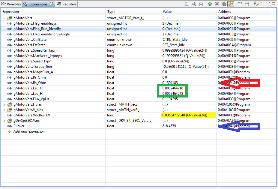
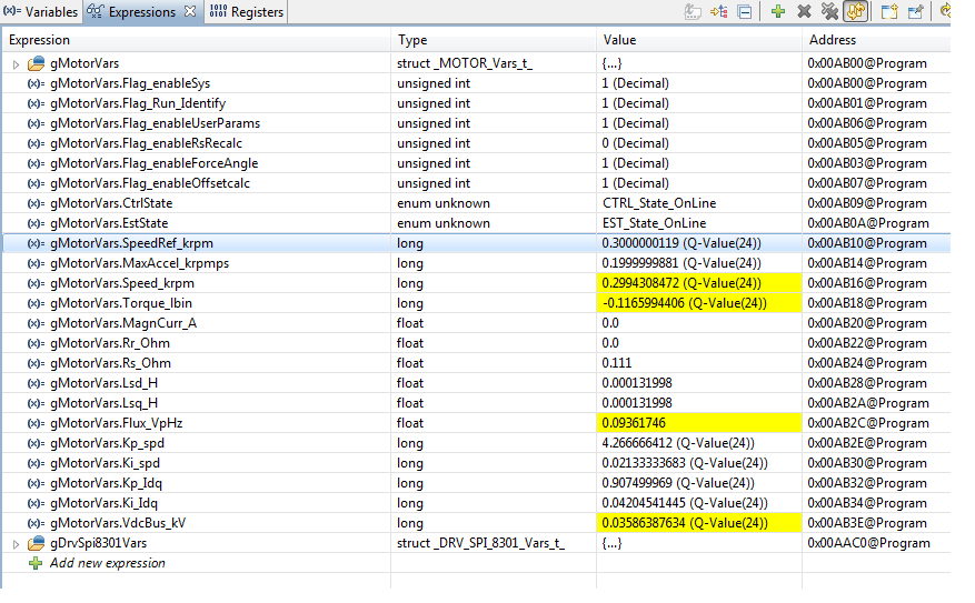
I am Julio Hernandez from a Dutch company of embedded systems; I am in charge of the motor control for one project; we decided to use the TMS320F28062F, which includes INSTASPIN-FOC. We bought a DRV3801 evaluation module for verify the performance with our motor (the parameters from the motor are attached). I measured the parameters using the InstaSpin reference manual and I compared it with the estimation of the Lab2a of Instaspin and just the Inductance was not the same (my measure with a RCL meter at 100 Hz= 330uH phase to phase; InstaSpin estimator= 320uH phase to neutral).

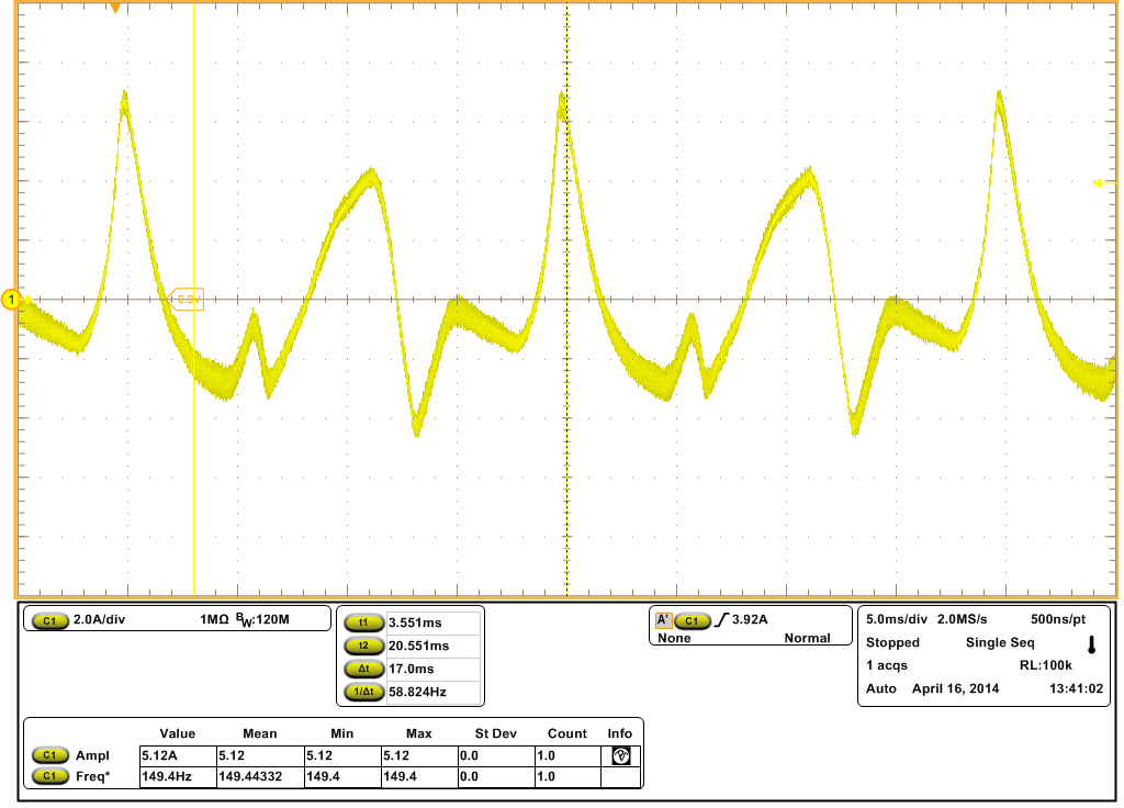
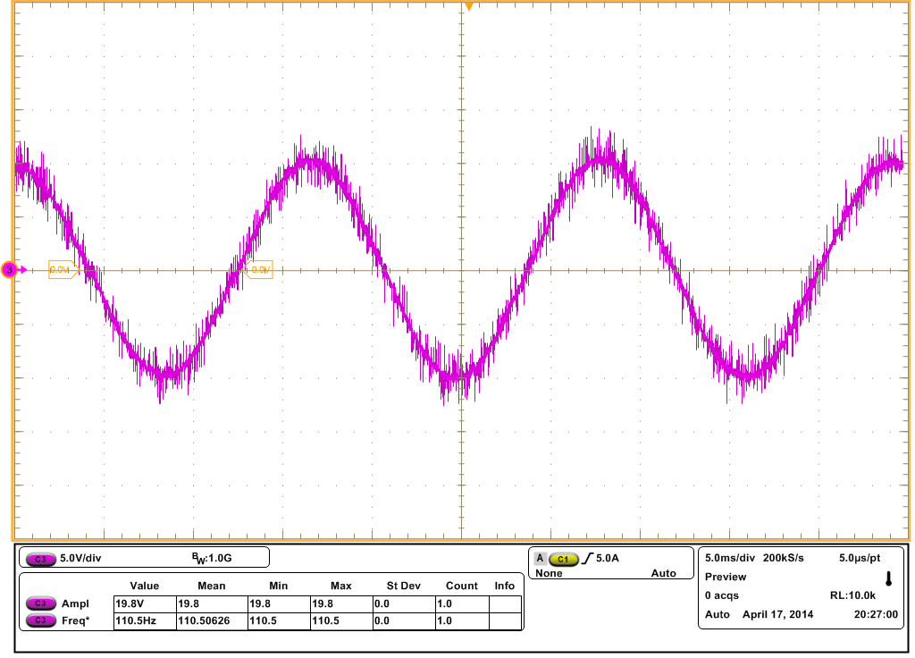
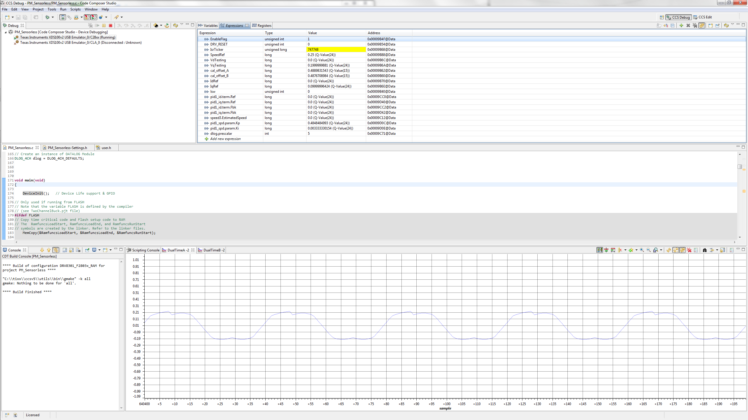
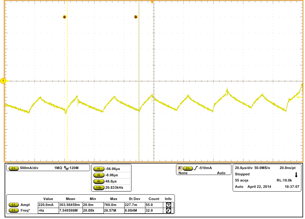
We want to use a PWM signal of 20kHz and a control loop of 10kHz, I configured the user.h file (the parameters are attached) and after some tests the rotor started to spin. The phase current U is showed below; the back EMF of the motor is sinusoidal, so I was expecting a phase current with a sinusoidal shape, but it did not.

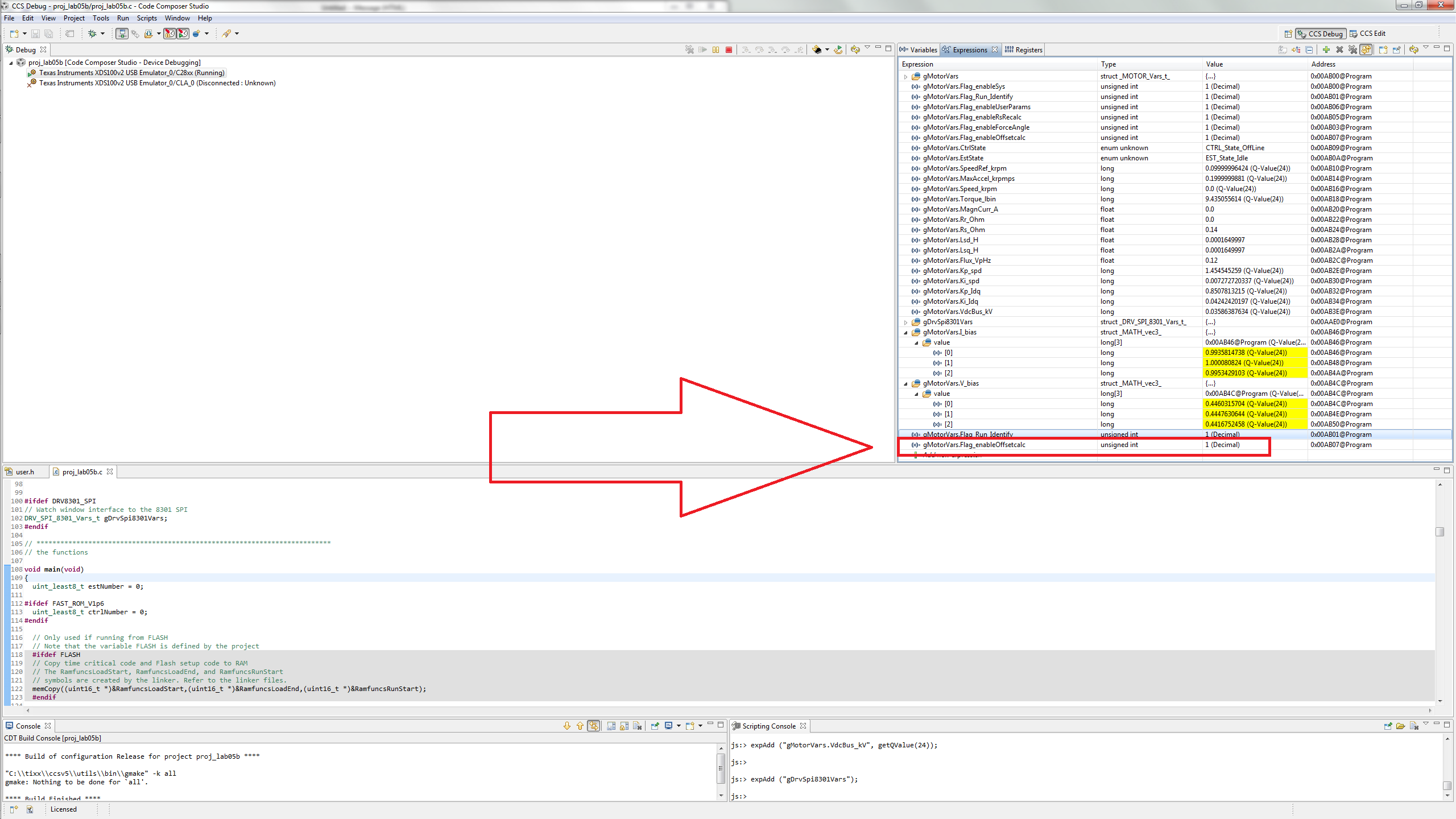
I was trying to tune the PI controllers of the Lab5a and Lab5b in order to obtain the sinusoidal shape, but I did not have success. I think, the shape is caused because the magnetic saturation of the machine; I verified the PI controller for the d current (Id) and I found that the parameters are the same as the PI controller for q current, is it correct?.

What do you recommend to do for the next step?

Figure 1. Phase current U, the speed control is set at 100 RPM, no load applied

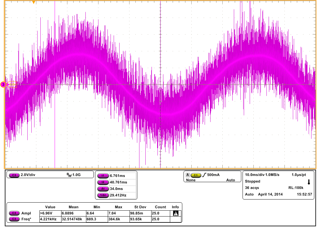
Figure 2. Phase current U, the speed control is set at 200 RPM, no load applied

Figure 3. Phase current U, the speed control is set at 400 RPM, no load applied

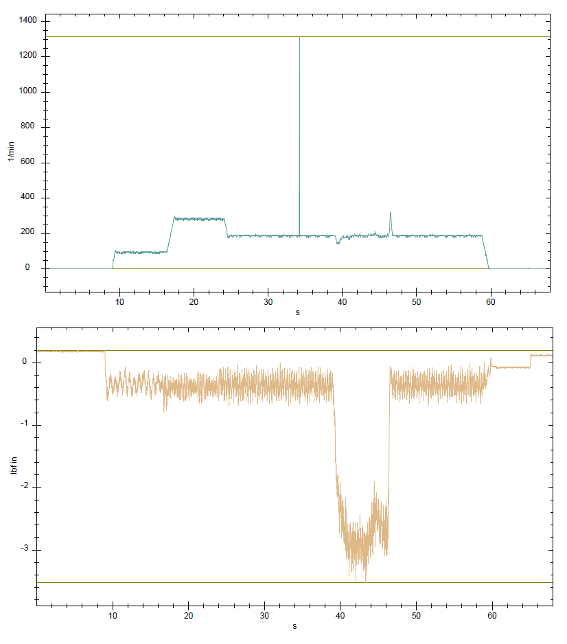
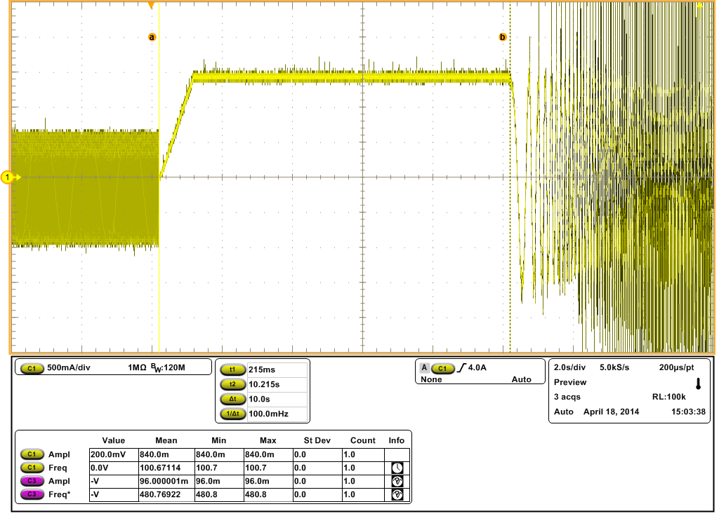
Figure 4. Phase current U, the speed control is set at 400 RPM, load applied


  • Could you make sure you have the offset calibration enabled? You can check with this value, it has to be set to 1.

    controller_obj->flag_enableOffset

    Also, check the offset values that it calibrated by checking these IQ24 variables:

    -Jorge

  • Hi Jorge

    Thanks for the reply. Yes, the Flag_Run_Identify is set to 1, the figure bellow is a printscreen from the test. I made several test with Flag_Run_Identify=true and Flag_Run_Identify= false, but the phase current still does not look like a sinusoidal shape. Only when the load is applied, the current changed its shape. What do you think? Could you see my user.h file, just for verify if something is wrong?

    Thanks


    Figure 1. Flag_Run_Identify= true, print screen of CCS

    Figure 2. Phase current U, speed controller set at 100 RPM, no load applied

    Figure 3. Phase current U, speed controller set at 100 RPM, load applied

  • you have a massive short circuit current of over 1500A.  I think you need to run your PWM faster and it probably wouldn't hurt to run your current loop faster as well.


  • Hi Chris

    Thanks for the reply, Where can I change the short circuit current? Is it in the user.h file? I increased the PWM frequency to 30kHz and 60kHz but the current signal has the same shape.

  • Short circuit current is inherrent to your motor design.

    Isc = Flux (in wB, or covert from V/Hz divided by 2*pi) divided by Ls

    1. are you sure your parameters are correct?  It is a very large flux and a very small Ls.

    2. If they are close to correct, as stated you certainly need to PWM faster.  Have you looked at the outputs of your competitor's controller to see what PWM rate they use?  Can you post a scope of their current waveform in the same conditions?


  • Hi Chris

    These are the answers:

    1. Are you sure your parameters are correct?  It is a very large flux and a very small Ls.

    Using the Isc equation:

    Isc= Flux(V.s) / Ls (H) = 0.019/0.000165= 115.15 A

    Isc= (Flux(V/Hz) / 2*pi) / Ls (H) = (0.12/2*pi) / 0.000165= 115.74 A

    I agree, it is a very large flux in reference with the stator inductance; unfortunately the manufacturer does not count with the parameters data (Rs, Ls and PMflux). I obtain these data from the back-EMF signal of the motor, the figures below show the voltage measured with the oscilloscope. 


    Figure 1. Phase to Phase back-EMF signal at 100 RPM

    Figure 2. Phase to Phase back-EMF signal at 300 RPM

    I obtain the inductance from a LCR meter with a frequency of 200Hz (which is greater that the maximum electrical frequency of the motor, Electrical Frequency= Maximum Speed*Pole Pairs / 60= 900*10/60=  150Hz) the result is Ls= 330uH and Rs= 324mOhms phase to phase. I don’t know if the machine is salient poles or non-salient poles, I am using the average of the measurements with the LCR meter.

    If they are close to correct, as stated you certainly need to PWM faster.  Have you looked at the outputs of your competitor's controller to see what PWM rate they use?  Can you post a scope of their current waveform in the same conditions?

     I don’t have a sample from other controller, we have choosen this motor about its low cost and InstaSpin for the FAST feature for a sensoless control scheme.


    Do you think that I am measuring the parameters in a wrong way?

    What do you recommend to do?

  • in the first post you said:

    InstaSpin estimator= 320uH phase to neutral

    but in your user.h  you use:

    USER_MOTOR_Ls_d                 (0.000165)

    which is correct?


    and then in user.h you have

    #define USER_IQ_FULL_SCALE_VOLTAGE_V      (50.0)

    but you are using

    #define USER_MOTOR_RATED_FLUX           (1.6011)

    This means you will overflow this variable at 50V /  1.6 V/Hz = 31.25 Hz = 187 RPM


    This sort of flux is seen from high voltage motors....not something you would run on a 60V kit.


    And it's still pretty strange to see a flux this high with an Ls this low, it makes for a massive switching current, which I think is distorting things at the low end every time you try to switch the PWM.


  • 4628.user.h

    Hi Chris

    Currently, I am using the stator inductance measured from the LCR meter (Lsphasetophase= 330uH; Lsphasetoneutral= 165uH and Rsphasetophase= 324mOhms; Rsphasetoneutral= 160mOhms). I showed the data given by InstaSpin because It was different in the Lab2a only in the inductance estimation, the others were almost the same.

    You are right, I forgot to update that user.h file, the currently file is attached, I am sorry. I have always been using the next parameters:

    #elif (USER_MOTOR == MY_MOTORS)
    #define USER_MOTOR_TYPE                 MOTOR_Type_Pm
    #define USER_MOTOR_NUM_POLE_PAIRS       (10)
    #define USER_MOTOR_Rr                   (NULL)
    #define USER_MOTOR_Rs                   (0.16)		
    #define USER_MOTOR_Ls_d                 (0.000165)
    #define USER_MOTOR_Ls_q                 (0.000165)
    #define USER_MOTOR_RATED_FLUX           (0.12)
    #define USER_MOTOR_MAGNETIZING_CURRENT  (NULL)
    #define USER_MOTOR_RES_EST_CURRENT      (2.5)
    #define USER_MOTOR_IND_EST_CURRENT      (-1.5)
    #define USER_MOTOR_MAX_CURRENT          (11.0)
    #define USER_MOTOR_FLUX_EST_FREQ_Hz     (40.0)

    With these parameters 50V/0.12(V/Hz)= 416.66 Hz= 2499.96 RPM, the maximum speed of the motor is 1225.5 RPM; is it ok?

    I have a doubt in this line:

    //! \brief Defines the R/L estimation frequency, Hz
    //! \brief User higher values for low inductance motors and lower values for higher inductance
    //! \brief motors. The values can range from 100 to 300 Hz.
    #define USER_R_OVER_L_EST_FREQ_Hz (300) // 300 Default

    If I use my parameters Rs/Ls= 0.160/0.000165= 969.69 Hz, but the maximum value is 300Hz; is it the problem?

  • ok, these parameters make much more sense!

    USER_R_OVER_L_EST_FREQ_Hz

    is not a maximum, it's the frequency of the single used for initial high frequency R and L esimation in EST_STATE RoverL.

    300 is too high for this motor (it is required for the really high frequency hobby motors that everyone seems to be testing with), so for your case you can reduce to (100) or (200).  This should help you to ID and you should be able to ID just fine with proj_lab2a. 

    When you run 2a look at controller_obl.RoverL (for 69M, use ctrl.RoverL for 27F) and you will see the RoverL value that is calculated with this injection.  It appears that you should expect something in the 1000 range.  If you see the value hit 2000.0 it has saturated and proj_lab2c should be used for ID.  This motor shouldn't do that though.


  • reposting correct user.h

    4628.user[1].h
  • Hi Chris

    I made a test in the Lab2a with your suggestions in the user.h file, but the phase current shape is still non-sinusoidal. The figure below shows the behavior of the motor.

    Figure 1. Phase current U with speed controller at 300 RPM

    As we were expected the RoverL value is around the 800 Hz, the estimation is Rs= 0.139Ohms, Ls= 0.000246H and PMflux= 0.11942; but, if the RoverL and Rs values are used for solving the Ls value:

    RoverL= Rs/Ls --> Ls= Rs/RoverL= 0.1394183/818.4579= 0.00017034 H this is closer that the value obtained with the LCR meter, Is it correct?

    Figure 2. Print screen of the CCS at the estimated parametes from Instaspin

    What do you recommend to do in the following test?

    Thanks in advance

  • use the 170uH value

    But this has to be a hardware issue....this isn't a difficult motor at all. 

    Can you go back to using the DRV8301 EVM with this motor? The DRV8301 EVM isn't that great by any stretch...but it should prove out that it works.


  • Hi Chris

    I have always been using the DRV8301-HC-EVM Rev D (TMS320F28069M). I put the Ls= 0.00017 H, but in the lab5a and lab5b the phase current is the same (non-sinusoidal)

    Do you think that something in my EVM is broken and it is generating an error in the measuring and then in the calculation of the motor control?

    What do you recommend to do?

  • you see the same waveforms with the DRV8301 and the same motor?

    can you try a different motor...let's prove both HW is working fine first.

  • Hi Chris

    I made all the tests using the DRV8301 EVM; the hardware prototypes for the project will be ready in two weeks. I made the test with another motor, this one has similar parameters than the last one (PMSM, 10 Pole pairs, Rated torque 7 N.m). Using the LCR meter, at 300 Hz, the Rs= 0.279Ohms and Ls=0.000303H in a phase to phase measuring.

    Figure 1. Photograph of the LCR meter at 300 Hz

    On the other hand, the PM flux was calculated using the back-EMF signal at 100 and 300 RPM, the result is PMFlux= 0.099 V/Hz.

    a) 

    b)

    Figure 2. The back-EMF signal obtained at a) 100 RPM and b) 300 RPM

    Using the Lab2a from InstaSpin, the estimation is Rs= 0.1110547, Ls= 0.0002209333 and PMFLUX= 0.09422; as with the other motor, only the Ls is different.

    Figure 3. PrintScreen of Lab2a parameters

    The RoverL=835.4614, and solving for Ls= Rs/RoverL= 0.1110547/835.4614= 0.000132H, almost the same than the LCR meter.

    Meanwhile, I tested the motor using the Lab5b using the Rs and PMFlux delivered by InstaSpin and the Ls calculated above; unfortunately the shape of the phase current is non-sinusoidal.

    a)

    b)

    Figure 4. Motor 2 at speed controller in the Lab5b of InstaSpin, a) printscreen of the parameters and b) phase current U at 300RPM

    What do you think?

  • This is strange...I'm surprised the motor runs at all if that's really the phase current.

    1. How are you measuring the phase current? Is this a calibrated current probe?

    2. Please go through motor ID process again, and please capture scope plots of the currents during

    EST_State RoverL

    EST_State Rs

    These should be very clean signals

    Attach the user.h you use just in case I missed something.


  • 7585.user.h

    Hi Chris

    Yes, the rotors are spinning and both have very high torque, I am surprised too. The speed estimation and the torque estimation are very close to the measuring with a torque sensor coupled in the shaft of my testbench. The figure below shows the Speed and Torque plots from the toque sensor interface.

    Figure 1. Speed and Torque plots from the toque sensor interface

    Answering to your questions :


    1. How are you measuring the phase current? Is this a calibrated current probe?


    Yes, it is a calibrated current probe, I made test with three probes and two different models of oscilloscope and the result is always the same. I verified the current shape measuring the TP25, which is the proportional drop voltage in the Rshunt caused by the current in the phase U (Motor 01). The figures below show the comparison between both signals.


    Figure 2. TP25 from the DRV830x_REVD_HWDevPKG\Schematic


    Figure 3. Comparison between current probe and TP25 voltage


    2. Please go through motor ID process again, and please capture scope plots of the currents during


    I verified the parameters suggested in the chapter 6 of TMS320F2806xF InstaSpin-FOC, I made a change in the USER_MOTOR_RES_EST_CURRENT from 2.5 to 1.5 (the user.h file is attached); the plot of the fisrt part of Lab2a is showed below:

    #elif (USER_MOTOR == MY_MOTOR01)
    #define USER_MOTOR_TYPE                 MOTOR_Type_Pm
    #define USER_MOTOR_NUM_POLE_PAIRS       (10)
    #define USER_MOTOR_Rr                   (NULL)
    #define USER_MOTOR_Rs                   (0.1394183)
    #define USER_MOTOR_Ls_d                 (0.000170)
    #define USER_MOTOR_Ls_q                 (0.000170)
    #define USER_MOTOR_RATED_FLUX           (0.1194295)
    #define USER_MOTOR_MAGNETIZING_CURRENT  (NULL)
    #define USER_MOTOR_RES_EST_CURRENT      (1.5)
    #define USER_MOTOR_IND_EST_CURRENT      (-1.5)
    #define USER_MOTOR_MAX_CURRENT          (11.0)
    #define USER_MOTOR_FLUX_EST_FREQ_Hz     (20.0)

    Figure 4. InataSpin Lab2a estimation process

    EST_State RoverL


    In the EST_State RoverL, the high frecuency injected has the configured frequency but the amplitude of the signal is not symmetric; the figure 5 shows the difference between the positive side and the negative side.

    Figure 5. Difference of the magnitude between the positive and the negative side signal from the RoverL process


    EST_State Rs


    In the EST_State Rs, the magnitude of the DC current applied corresponds with the USER_MOTOR_RES_EST_CURRENT=1.5 and the time (10s) configured in the user.h and user.c files respectively.

    Figure 6. EST_Sate Rs process

    1.- Do you think that the difference between the amplitude (positive and negative) in the EST_State RoverL process is a symptom of something?


    2.- In the the chapter 6 of TMS320F2806xF InstaSpin-FOC the plot in the figure 6-15 shows a period of 7s for the EST_State Rs process, Do I have to change this value in the user.c file?

    Thanks in advance

  • Hi Chris

    Today I tried something different, I used the PM_Sensorless project from CONTROLSUITE and I couldn’t pass from the “Level 1A (SVGEN_MACRO Test)”, I was expecting to see the SVM signals in the Graph tool of CCS and the DACPWM ports in the DRV8301 (J6) but it did not happen; the figure 1 shows the result (I forgot to take a plot from the oscilloscope, but it was the same that the Graph tool of CCS)

    C:\ti\controlSUITE\development_kits\DRV830x-HC-C2-KIT_v105\PM_Sensorless


    Figure 1. Level 1A (SVGEN_MACRO Test) of the PM_Sensorless project running on DRV3801 EVM

    However, I made the same test with other development kit from one of my colleagues (general purpose docking from texas instruments), in this case I only can see the Graph tool (it is not a DRVXXX EVM), the result is in the figure 2.

     http://www.ti.com/tool/tmdscncd28069


    Figure 2. Level 1A (SVGEN_MACRO Test) of the PM_Sensorless project running on general purpose kit

    Could you confirm if the same project can be run in both DSP?

    If it is an affirmative answer, Do you thing that something in my DSP is wrong? Using the InstaSpin Labs the motors are spinning, but if the SVM signal is not generated in the properly way, It could be the reason for the non-sinusoidal phase current.

    What do you think?

  • The RoverL current not being symmetrical is a concern.

    Could you confirm your compiler version? We had an issue with 6.2.0, 6.2.1 and 6.2.2, so you have to avoid those versions. You can see the compiler version by right-click the project, build settings

    Keep in mind that some times there are two columns, one showing the intended compiler version, and one showing the "effective" compiler version. The effective is the one that was actually used. If the effective version is not at least 6.2.3, download newer versions of the compiler under Help - Check for Updates:

    Let's first see if it is a compiler issue.

    -Jorge

  • Hi Chris and Jorge

     I made the changes suggested by Jorge and the phase current starts to look sinusoidal. I had a Compiler 6.2.3 (I thought  that it was enough) and I update it to 6.2.6, the figure below shows the before and after the updates:

    Figure1. PrintScreen a) Before the updates and b) After the updates 

     The phase current at 300 RPM with and without load looks like this:

    a) 

    b)

    Figure 2.- Phase current U with a speed controller at 300RPM a) whitout load and b) with load applied

    I think that this problem is solved, thank you so much guys.


    I still having some doubts (Do I have to make another post?):

     1.- I rebuild the PMsensorless project after the updates of the compiler and the SVM signal still without a proper shape with my TMS320F28069MISO control card, How is it possible? Is it still something wrong?

     2.- The Lab2a is giving a Rs= 0.14 Ohms, Ls= 250uH and PMFlux= 0.119V/Hz with the Motor 01; one more time, the Ls is not close to the inductance measured by the LCR meter (165uH). However, the RoverL= 835.35 and with this data the Ls= 167uH. What is the appropriate value for INSTASPIN?

     3.- I made some test of speed and torque in the Lab5b and the estimation is very close to the data obtained with the Torque sensor mounted in the shaft. However, the frequency of the of the PWM signal is not fixed, it looks like two times the desired frecuency. The figure 3 shows the PWM signal at 7kHz and the speed controller at 100 and 500RPM respectively, since the figure 4 shows the PWM signal at 30kHz and the speed controller at 100 and 500RPM respectively. Is It correct?

    a)

    b)

     Figure 3. PWM signal at 7kHz and the speed controller at a) 100RPM and b) 500RPM 

    a)

    b)

     Figure 4. PWM signal at 30kHz and the speed controller at a) 100RPM and b) 500RPM

    Thanks one more time

  • your problem was that the EFFECTIVE compiler was still 6.2.0 which has the IQMath bug mentioned in the Sticky post.


    Julio Noel Hermandez said:

     1.- I rebuild the PMsensorless project after the updates of the compiler and the SVM signal still without a proper shape with my TMS320F28069MISO control card, How is it possible? Is it still something wrong?

    It may be that the project uses something in ROM that is not there (or in a different location) on f28069M

    Julio Noel Hermandez said:

     2.- The Lab2a is giving a Rs= 0.14 Ohms, Ls= 250uH and PMFlux= 0.119V/Hz with the Motor 01; one more time, the Ls is not close to the inductance measured by the LCR meter (165uH). However, the RoverL= 835.35 and with this data the Ls= 167uH. What is the appropriate value for INSTASPIN?

    what is your max speed (in Hz) again?  please upload your user.h

    in general it's always better to use the lower value...and I agree that the 250uH looks too large for this motor. 

    Julio Noel Hermandez said:
     3.-

    please upload your user.h before I comment.

  • 3113.user.h

    Hi Chris

    Yes, that was the problem, I am sorry.

    I re-calculate the parameters of the user.h (it is attached) file as you suggest, this time I used the maximum parameters from the motor with a headroom of 30%

    The USER_NUM_PWM_TICKS_PER_ISR_TICK=1 and the USER_NUM_ISR_TICKS_PER_CTRL_TICK=1.The parameters which suffered a change are listed below:

    #define USER_IQ_FULL_SCALE_FREQ_Hz        (266.0)
    
    #define USER_IQ_FULL_SCALE_VOLTAGE_V      (54.0)

    This time I set the reference speed at 100RPM and 800 RPM, as you can see in the figure 1 and 2 respectively. At 100 RPM the motor control frequency looks like 40 kHz, but in the 800 RPM test I saved to different frequencies(in the same test), the first one at 20 kHz and 40kHz

    Figure1. Speed set point at 100RPM

     a)

    b)

    Figure 2.- Speed set point at 800RPM, a) frequency of 20kHz and b) frequency of 40kHz

    What do you think? Am I measuring wrong?

  • attach the user.h you used for this please


  • user.h comments:

    #define USER_IQ_FULL_SCALE_FREQ_Hz        (800.0)
    I agree with your calculations for your motor, but it won't hurt to have this higher so let's leave it here for now.

    #define USER_IQ_FULL_SCALE_VOLTAGE_V      (36.0)
    Let's set this to your bus voltage to start. If your flux is very large we can raise this as required to insure no Bemf calculation (Flux * Hz)  overflows this value. I notice your comment that the max speed is 1.5 * the rated speed....the only way that is going to happen is if the motor is unloaded or you use field weakening.  Also a good reason to keep the FULL_SCALE_FREQ to a higher level. 

    Actually, after looking at the flux value in your USER_MOTOR of 0.12 V/Hz, this will support 300 Hz (1800 RPM) if using full modulation before field weakening is required. If youa re going to use field weakening let's update this

    #define USER_IQ_FULL_SCALE_VOLTAGE_V      (45.0)
    to give us a bit of headroom around 375 Hz.


    #define USER_PWM_FREQ_kHz                (15.0)
    Let's leave at 15 for now, this motor should NOT require higher

    #define USER_FORCE_ANGLE_FREQ_Hz            (4.0)
    Minor thing, but we should keep this value > 2* the value produced by USER_ZEROSPEEDLIMIT * FULL_SCALE_FREQ

    #define USER_MOTOR_FLUX_EST_FREQ_Hz     (30.0)
    Let's increase this just a bit to see if the Ls value changes much

    #define USER_MOTOR_RES_EST_CURRENT      (1.5)
    Does this value allow the motor to start spinning during RampUp state of Motor ID?


    This is an extremely straightforward motor. It should be easy to ID and easy to control. You can always improve the voltage and current hardware scaling to improve resolution, but it should run just fine on DRV8301.

    Try ID'ing with proj_lab02a or 2b again (2c should not be required for this motor). and see what happens.


    There is also no reason that you should be getting different timing....did you change any other files?  Maybe you should start with a fresh install of MotorWare _12 and drop in this user.h


    5466.user.h
  • 4578.user.h

    Hi Chris

    I made the changes that you suggested, I updated my motorware to the version 12, with this version some sections of the user.h are different (the user.h file is attached), I kept the default values placed in the file:

    #define USER_IDRATED_FRACTION_FOR_RATED_FLUX (1.0)      // 1.0 Default, don't change
    
    //! \brief Defines the fraction of IdRated to use during inductance estimation
    //!
    #define USER_IDRATED_FRACTION_FOR_L_IDENT    (1.0)      // 1.0 Default, don't change
    
    //! \brief Defines the IdRated delta to use during estimation
    //!
    #define USER_IDRATED_DELTA                  (0.0002)

    #define USER_MOTOR_FLUX_EST_FREQ_Hz     (30.0)
    Let's increase this just a bit to see if the Ls value changes much

    I tested the lab2a again and the results are: Rs=0.140 Ohms, Ls= 0.000230uH and PMFLUX= 0.12 V/Hz, the value in the USER_MOTOR_FLUX_EST_FREQ_Hz did not make a big difference in the Ls estimation. I am going to keep the Ls= 0.000165H value.

    There is also no reason that you should be getting different timing....did you change any other files?  Maybe you should start with a fresh install of MotorWare _12 and drop in this user.h

    I did not change other files, but I measured the output of the EPWM1A in the pin25 of the connector J5 in the DRV8301 EVM. The figure below show the result, I think that I was mixing the MOSFET signals, the PWM signal is always 15 kHz

    a)

    b) 

    Figure 1. Phase current U, speed controller set at 100RPM and the EPWM1A signal a) The total view of the phase current b) the zoom to the PWM frequency

    What do you think? Could I start the develop of our own project now? Thanks for all your help

  • it seems like you are now on a good path.

    proceed and let me know if you have any other problems.


  • Ok, I will let you know

    Thank you very much guys

  • Hi Chirs

    I have a doubt; we want to make our software solution in C++, but I am not sure if this is possible with the InstaSpin libraries. I verified that they are implementing the "extern" function but I read in other post that exist a bug in the MotorWare 11 for implementations on C++ compiler.

    Is it solved for the Motorware 12 libraries and the Compiler v6.2.6?

    Do you know about some application notes for this kind of implementations?

    Thanks

  • Julio,

    We don't test MotorWare for C++, so anything untested you should assume won't be 100% functional.  We tried to put most of the hooks in for C++, at least on the core control code....but I'm sure there are some driver issues.


  • Hi Chris

    When you said "We tried to put most of the hooks in for C++, at least on the core control code..." do you mean that the code of InstaSpin and FAST inside of the ROM memory can be used from a source code in C++?

    If I make the drivers and the harware abstraction layer (HAL) in C++, do you think that I can still using the InstaSpin solution in ROM or at least the FAST estimator?

    Thanks

  • Julio Noel Hermandez said:

    When you said "We tried to put most of the hooks in for C++, at least on the core control code..." do you mean that the code of InstaSpin and FAST inside of the ROM memory can be used from a source code in C++?

    We think we have proper protocol in all the core MotorWare project files, proj_lab##.c, user.c, user.h, main.c, ctrl.c/.h etc.  But we haven't compiled for C++ so we don't know for sure.  I expect we probably missed something....and I very much expect that there are some issues with the \drivers files as they are not up to the level I thought they were originally.

    Julio Noel Hermandez said:

    If I make the drivers and the harware abstraction layer (HAL) in C++, do you think that I can still using the InstaSpin solution in ROM or at least the FAST estimator?

    That should be possible.


  • Hi Chris


    Thanks for your reply,
    What do you recommend to do at first, try to make compatible the C++ and C libraries or make the drivers in C++?

  • I'd just try compiling with any C++ additions in the proj_lab## and other \src files