Hi,
I am facing unexpected problem in downloading code to my newly designed board using SCI I/F. The schematic is the same, as on the previous board on which I was always able to download my code using SCI I/F and C2Prog software. The previous layout was done using two layers. The current board has four layers to reduce the size (one layer for GND and one for 3.3V). On the last design I have used the Silabs CP2104 instead of the CP2102 which gives a regulated 3.45V instead of the 3.3V. I thought at first that this could be a problem also I have disconnected the CP2102 of the former board and connected with flying leads the CP2104 and was able to download the code. Therefore I assume Silabs IC was not the problem, I have checked all wires of the new board without finding any short circuit or improper connection. Voltages measured on the new board on the CP28027 are:
VDDIO (PT#35) 3.30V, VDDA (PT#11) 3.29V, VDD18(PT#32) 1.92V, VDD(PT#43) 1.92V. As advised five 2.2uF and two Inductors of 60Ohms and 200hms are used. The transmitted signal is received on GPIO-28(SCIRX -PT#48) high 3.4V and low level 0.2V. But no answer on GPIO-39 (SCITX PT#1) can be seen the voltage on this pin remains at 3.3V.
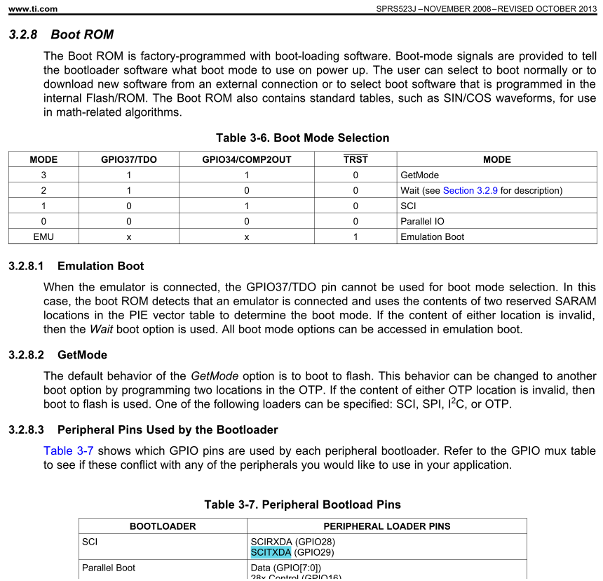
Other pins are connected as follows /VREGENZ 0V, XRS 3.3V (2k2), /TRST 0V, TDO 3.3V (2k2), GPIO-34 0V (2k2),
and ground pins connected to ground.
On both boards Ti regulator TPS73033 is used after the regulator of the CP210x which provides a little less than 100mA.
Has someone experienced the same issue ?
(Rk:The JTAG port is not available on the new board)
Is the layout very sensitive concerning the placement of inductors and 2.2uF capacitors ?
Concerning connections to GND or VDD for GPIO-34 & TDO, is there any precautions to be taken?
What are the possible root causes for not getting any feedback from TX on F28027? (during the autobaud process of C2PROG software) when the transmitted bits are seen on RX)
Any idea of what has to be checked further?
Thank you in advance for your advices and for your time,
Regards,
Olivier