This thread has been locked.

If you have a related question, please click the "Ask a related question" button in the top right corner. The newly created question will be automatically linked to this question.

Delfino C28346 eCAN Example Code Problems

Other Parts Discussed in Thread: CONTROLSUITE

I'm attempting to execute the ControlSUITE v3.2.6 example project "Example_28xEcan_A_to_B_Xmit" on a Delfino C28346 DIM168 Experimenter's Kit. The example configures the eCANA module to operate at 1Mbit/s, and sets the message ID and data fields of a continuously repeated packet as follows:

ECanaMboxes.MBOX25.MSGID.all = 0x95555555;
ECanaMboxes.MBOX25.MDL.all = 0x55555555;
ECanaMboxes.MBOX25.MDH.all = 0x55555555;

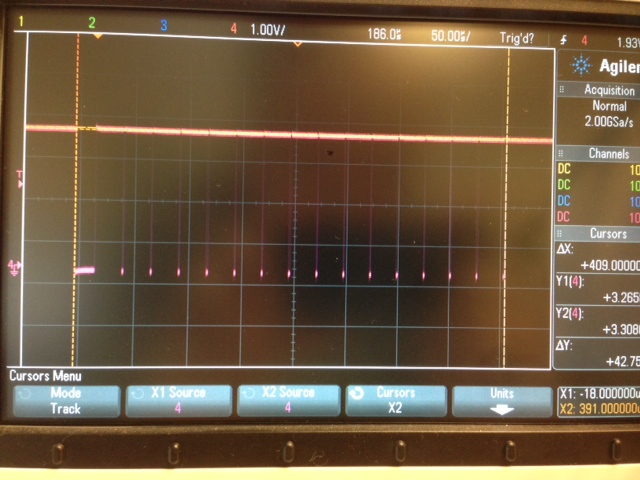
However, a scope trace of the CANA TX pin (below) shows that this code does not appear to produce the expected message. Changing the message ID and data fields has no effect on the output waveform. 

Peripheral clocks are enabled and the eCANA module appears work through the configuration steps properly. Again, this is strictly the example code from ControlSUITE... I'm looking for any help or suggestions.

Thanks,
Jonathan

  • Jonathan,

    I am leaning towards suspecting a hardware issue. Have you ensured the two CAN modules are properly connected to each other and the termination resistors are in place? Is it possible to post a photograph of your setup? Even assuming the two modules are not connected to each other properly, you should see a proper waveform up until the acknowledge phase of the frame. If the ACK is not coming from the receiving node, the transmission will be attempted over and over again. If your scope has the ability to trigger on a CAN frame, set it to trigger on a SOF bit and capture the waveform. Make sure the bit time is 1 uS. If you are able to see this, we can move to the receive side.

  • Hareesh,

    Thanks for the response. The issue was indeed caused by a hardware configuration error. I incorrectly assumed that the primary purpose of CAN bus termination resistors was for signal integrity and thus didn't have them installed in my small test setup - I did not realize that the bus termination resistors are what drive the recessive bus state (and not the CAN driver directly).

    Thanks,

    Jonathan

  • Jonathan,

    The primary purpose of the termination resistors is to reduce signal reflections. Reduce the bit-rate to 50 kbps (or lower) and attempt communication between the two nodes without the terminators and share your observations.

    You may be interested in reading an excellent app.note about the CAN physical layer written by my colleague. The lit # is SLLA270. You can download it from the TI website.