This thread has been locked.

If you have a related question, please click the "Ask a related question" button in the top right corner. The newly created question will be automatically linked to this question.

F28031 - Ramp Generator issues

Other Parts Discussed in Thread: CONTROLSUITE

Hi,

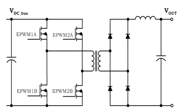
I have a problem between the RAMPSTS register value and the 10-DAC set value. First of all I use the contoller to control a buck converter, also I configure the ramp and the comparator as fallow:

/* Configure the comparator: if A > B -> 1, else -> 0 */     

            SysCtrlRegs.PCLKCR3.bit.COMP2ENCLK = 1;   /* Enable clock to the Comparator 2 block */

            Comp2Regs.COMPCTL.bit.COMPDACEN = 1;      /* Power up Comparator 1 locally */

            Comp2Regs.COMPCTL.bit.COMPSOURCE = 0;     /* Connect the not inverting input to the internal DAC */ 

            Comp2Regs.COMPCTL.bit.CMPINV = 1;         /* Inverted output of the comparator is passed */

            Comp2Regs.DACVAL.bit.DACVAL = 0;        /* Set DAC output to midpoint */  

            Comp2Regs.COMPCTL.bit.SYNCSEL = 0;        /* Asynchronous version of the comparator

            Comp2Regs.COMPCTL.bit.QUALSEL = 1;        /* Input to the block must be consistent for x+1 consecutive clocks */

            Comp2Regs.DACCTL.bit.RAMPSOURCE = 4;      /* Ramp source is ePWM5 */

            Comp2Regs.DACCTL.bit.DACSOURCE = 1;       /* With ramp generator */

            Comp2Regs.RAMPDECVAL_SHDW = 8;

Assume that I set the RAMPMAXREFS = 12800 and also I set the RAMPDECVALS = 8.

My issue is:

In debug mode:

- I observe that the RAMPSTS is decreasing each SYSCLK (60MHz) by the value into RAMPDECVALS, but in debug mode I can't use the power output so the comparator input voltage sense is alway at 0, so in this case the PWM is limited by software event qualifier.

- The RAMPSTS is reset at each 96kHz as set by the PWM5 who is TBCLK = 624, see PWM5 setup below:

EALLOW;
{

/* Timer setup preset, clear and phase */
EPwm5Regs.TBPRD = ( 624 ); /* Set PWM period 96kHz @ 60MHz clock */
EPwm5Regs.TBPHS.half.TBPHS = 0x0000; /* Set phase register to zero */
EPwm5Regs.TBCTR = 0x0000; /* Clear counter */

/* Setup TBCLK */
EPwm5Regs.TBCTL.bit.CTRMODE = TB_COUNT_UP; /* UP count which is asymmetrical mode */
EPwm5Regs.TBCTL.bit.PHSEN = TB_DISABLE; /* Phase loading desable */
EPwm5Regs.TBCTL.bit.HSPCLKDIV = TB_DIV1; /* Clock ratio to SYSCLKOUT is Divide by 1 */
EPwm5Regs.TBCTL.bit.CLKDIV = TB_DIV1; /* Div by 1. TBCLK = SYSCLKOUT / (HSPCLKDIV * CLKDIV) */
EPwm5Regs.TBCTL.bit.PRDLD = TB_SHADOW; /* Set shadow register load */

/* Setup Counter-Compare */
EPwm5Regs.CMPCTL.bit.SHDWAMODE = CC_SHADOW; /* Load shadow register CMPA every ZERO */
EPwm5Regs.CMPCTL.bit.SHDWBMODE = CC_SHADOW; /* Load shadow register CMPB every ZERO */
EPwm5Regs.CMPCTL.bit.LOADAMODE = CC_CTR_ZERO; /* Active CMPA load from shadow mode when CTR = Zero */
EPwm5Regs.CMPCTL.bit.LOADBMODE = CC_CTR_ZERO; /* Active CMPB load from shadow mode when CTR = Zero */

/* Configure the deadband submodule */
EPwm5Regs.DBCTL.bit.IN_MODE = 0; /* PWM1A is the DB source for rising/falling edge */
EPwm5Regs.DBCTL.bit.OUT_MODE = 0; /* The rising-edge delayed signal is seen on output EPWMxA */
EPwm5Regs.DBRED = DEAD_BAND_RISING; /* Rising edge delay */

/* Enable TZ1 as trip source */
EPwm5Regs.TZSEL.bit.OSHT1 = TZ_ENABLE;

/* Enable one shot interrupt (uncomment if useful) */
EPwm5Regs.TZEINT.bit.OST = 1;

/* Force all PWM outputs at low state when trip occurs */
EPwm5Regs.TZCTL.bit.TZA = TZ_FORCE_LO;

EPwm5Regs.AQCTLA.bit.ZRO = AQ_SET; /* When AQCTLA = Zero set EPWMxA output high */

EPwm5Regs.CMPB = 312; /* CMPA event when it reaches this value */
EPwm5Regs.AQCTLA.bit.CBU = AQ_CLEAR; /* CMPA: Set (variable) */

}

EDIS;

- When I disengage the debug mode and I use my output power, at the input sense voltage I observe triangular wave form as expected, although then I previously observe the RAMPSTS register desreasing during an half cycle of my full bridge PWM, the comparator is still triggering at the RAMPMAXREFA = 12800 -> 10 bit MSB = 200. That is special for my point of view, but I think I missed a configuration, but I can find it.

If you need more information, I can give it to you, but I will need to have a private room with you, because I can write into this forum some sensitive information.

Regards,

Marc-Olivier Brassard, Jr. Eng.

Electronic designer 

  • Marc-Olivier,

    Just to eliminate an easy solution possibility, have you looked at this appnote?

    http://www.ti.com/lit/sprabe7

    and associated code:

    http://www.ti.com/lit/zip/sprabe7

    Regards,

    David


  • Davis,

    Yes I looked previously this application note, and it should be our type configuration when I will be able to use the ramp generator. For now I don't use the feedback signal from the output of the buck I'm only try to validate the interaction between current sensor at the input and the comparator signal with ramp down DAC value. Is that could be my issue? Do I need to have the feedback from the output to integrate the ramp generator?

    Note that the ramp set value is manually calculated by me with similar equation then show into your application note. I determine my inductor current slope and then I translate that slope to have the ramp desire value.

    The DC source is generated by a full bridge with mosfet and a transformer with a certain ratio. The PWM is control at the primary side of the transformer where the voltage is 400V. The secondary side have a voltage of 654V and the current ripple into the inductor should be between 12A to 8A.

    The PWM of the full bridge have a time base of 1250 (48kHz) and then during the half cycle we have the PWM1 and the PWM4 activated and for the other half it is the PWM2 and the PWM3 who are activated.

    We need a ramp down during each half of the full bridge switching frequency of 48kHz. It is why I create another PWM (PWM5) who is synchronized with all other 4 PWM (I assume that) but with a time base of 625 (96kHz). That kind of coding seems to us non orthodox way to do, but for now it is the only way I had to synchronize the shadow register and the active register of the ramp generator block diagram.

    But I think we had done exactly like it is explain into the application note that you talking about except for the output feedback design (this feedback could be integrate if needed)

    If you have any other question about my answer or the issue, don't hesitate!

    Regards,

    Marc-Olivier Brassard Jr. Eng.

    Electronic designer 

  • Marc-Olivier,

    Hmmm.  Have you looked at the slope compensation approach used in the Digital Power Workshop?

    http://processors.wiki.ti.com/index.php/C2000_DPSWorkshop

    - David

  • Davis,

    I begin this morning by listening to the proposed workshop, to make sure we didn't mist any important information. I observe a major difference between what we do what TI did into the work shop.

    The difference is hardware, we use all four PWMxA to driver our full-bridge, but in the work shop TI use PWMxA for top mosfet and PWMxB for bottom mosfet.

    Is that a problem that we do not use PWMxA for top mosfet and PWMxB for bottom mosfet?

    Marc-Olivier

  • Hi Marc-Olivier,

    It looks like you are controlling a phase shifted full bridge power stage with peak current mode control. In this case you will need 4 PWM outputs to drive 4 power electronic switches that form the full bridge. The DPS workshop kit controls a non-isolated DC-DC buck stage, where only a PWMA output is used (Lab3 & Lab4 implement peak current mode control).

    We have a 600W HVPSFB kit (http://www.ti.com/tool/tmdshvpsfbkit) that implements this topology and control technique. You can download all software and documentation as part of the controlSuite download (http://www.ti.com/tool/controlsuite). In this case we use PWMs 1A, 1B, 2A, 2B for driving the full bridge switches and 4A, 4B for driving the synchronous rectifier switches.

    I hope this helps.

    Hrishi

  • Hi Hrishi,

    Effectively we try to control a phase shifted full bridge power stage with the peak current mode control, but this shifted full-bridge is controlling the buck converter, like below:

    source: http://processors.wiki.ti.com/index.php/C2000_DPSWorkshop

    I try to determine our slop compensation problem, so I listened to the DPSWorkshop as recommended. After listening, I'm wondering if we made a hardware connection error, so is it essential that we use EPWMxA for top mosfet and EPWMxB for bottom mosfet, or is doesn't matter?

    In other hand, when I implement the slope compensation design, I have some an issue with what I observe in debug mode and what is really apply to the comparator negative input. I observe the RAMPSTS ramping down at each SYSCLK. How do I validate it?

    ex.

    1) I set the RAMPDECVAL_SHDW register to a value of 5.

    2) I set the RAMPMAXREF_SHDW register to a value of 400.

    3) I enable Target clock and I reset the CLK value at the beginning of the interrupt configuration.

    4) I run the software until I return to the beginning of the interrupt.

    5) I evaluate the cycle count and I determined that the  RAMPDECVAL is subtract by n SYSCLK from the value of RAMPSTS as expected. 

    What I can explain is that RAMPSTS 10 MSB seem not to be transfert into the DAC, because I observe the COMPxTRIP flag during our test and the comparator triggering an event only when the current sense reach the RAMPMAXREF value rather than when it reach the RAMPSTS 10 MSB as explain into SPRUGE5F.

    All ramp generator register configuration are done as recommended into SPRUGE5F, but is there a non-documented configuration we mist but would be used in librairy DPLib?

  • Hi Hrishi,

    At this moment I think we find our problem. I previously said that I use the EPWM5 as the RAMPSOURCE PWM. After few tests my colleague determine that the EPWM5 must be shifted by the length of the blanking window. We try it and then I observe the deactivation of the PWM under the RAMPMAXREF value. So far I have not observed this phenomenon. I do not have the exact expected value when the PWM is shutdown by the comparator COMPSTS.

    So I wonder if my perception is correct, I think RAMPSTS register is decremented by the value of RAMPDECVAL register every cycle of the system clock (set to 60MHz), is this true?

  • Yes, after a PWMSYNC event the value of RAMPDECVAL_ACTIVE is subtracted from RAMPSTS on every SYSCLK.

  • Hi Hrishi,

    Effectively I confirm that I have a subtraction at each SYSCLK of the RAAMPSTS register with the value of the RAMPSDECVAL_ACTIVE register, my timing issues is directly links to the signal buffer plus the ADC hysteresis.

    Thank you very much for your help and also for Davis help!

    Marc-Olivier