This thread has been locked.

If you have a related question, please click the "Ask a related question" button in the top right corner. The newly created question will be automatically linked to this question.

Slow F28026

Other Parts Discussed in Thread: TMS320F28026, CONTROLSUITE

Hi,

I'm programming a TMS320F28026 and am suspecting a wrong CPU configuration or calibration. I am setting the following:

    CLK_setOscSrc(handles.clk, CLK_OscSrc_Internal);
    ....
    PLL_setup(handles.pll, PLL_Multiplier_12, PLL_DivideSelect_ClkIn_by_2);
    PLL_enable(handles.pll);
    ....
    EALLOW;
    SysCtrlRegs.PCLKCR0.bit.ADCENCLK = 1;
    (*Device_cal)();
    SysCtrlRegs.PCLKCR0.bit.ADCENCLK = 0;
    EDIS;

With this configuration, I get a timer that interrupts on the set timeout correctly and PWMs that have the correct frequency. This leads me to believe that at least the peripherals are clocked correctly.

On the other hand, I see very slow operations with relation to the ADC. The ADCs are configured as follows:

    ADC_enableBandGap(handles.adc);
    ADC_enableRefBuffers(handles.adc);
    ADC_powerUp(handles.adc);
    ADC_enable(handles.adc);
    ADC_setVoltRefSrc(handles.adc, ADC_VoltageRefSrc_Ext);
    ...

    /*
     * configure ADC itself
     *
     * Note: The first of each chain of conversions will be double sampled
     * to workaround the ADC 1st sample issue for rev0 silicon errata.  If the
     * results of a chain start with SOCX, then ADC_forceConversion with
     * ADC_SocNumber_(X-1) must be called.
     *
     * Note: the revision in use is 0 (read the microcontroller's errata)
     */
    ADC_setIntPulseGenMode(handles.adc, ADC_IntPulseGenMode_Prior);                            /* ADCINT* trips after AdcResults latch */
    ADC_enableInt(handles.adc, ADC_IntNumber_1);
    ADC_enableInt(handles.adc, ADC_IntNumber_2);
    ADC_setIntMode(handles.adc, ADC_IntNumber_1, ADC_IntMode_ClearFlag);                    /* Disable ADCINT1 continuous mode */
    ADC_setIntMode(handles.adc, ADC_IntNumber_2, ADC_IntMode_ClearFlag);                    /* Disable ADCINT2 continuous mode */
    ADC_setIntSrc(handles.adc, ADC_IntNumber_1, ADC_IntSrc_EOC3);
    ADC_setIntSrc(handles.adc, ADC_IntNumber_2, ADC_IntSrc_EOC5);
    ...
    ADC_setSocChanNumber(handles.adc, ADC_SocNumber_0, ADC_SocChanNumber_A6);                /* unused, there because of micro's bug */
    ADC_setSocChanNumber(handles.adc, ADC_SocNumber_1, ADC_SocChanNumber_A6);
    ADC_setSocChanNumber(handles.adc, ADC_SocNumber_2, ADC_SocChanNumber_B6);
    ADC_setSocChanNumber(handles.adc, ADC_SocNumber_3, ADC_SocChanNumber_A4);
    ...
    ADC_setSocChanNumber(handles.adc, ADC_SocNumber_4, ADC_SocChanNumber_B4);                /* unused, there because of micro's bug */
    ADC_setSocChanNumber(handles.adc, ADC_SocNumber_5, ADC_SocChanNumber_B4);

    ADC_setSocSampleWindow(handles.adc, ADC_SocNumber_0, ADC_SocSampleWindow_7_cycles);
    ADC_setSocSampleWindow(handles.adc, ADC_SocNumber_1, ADC_SocSampleWindow_7_cycles);
    ADC_setSocSampleWindow(handles.adc, ADC_SocNumber_2, ADC_SocSampleWindow_7_cycles);
    ADC_setSocSampleWindow(handles.adc, ADC_SocNumber_3, ADC_SocSampleWindow_7_cycles);
    ADC_setSocSampleWindow(handles.adc, ADC_SocNumber_4, ADC_SocSampleWindow_7_cycles);
    ADC_setSocSampleWindow(handles.adc, ADC_SocNumber_5, ADC_SocSampleWindow_7_cycles);

(The parts configuring the interrupts are omitted). This means that the ADC should take 7 clock cycles to complete. However, the process of setting the SOC, and waiting until the interrupt is received for the chain with 4 conversions, takes about 7 microseconds! I measured this by toggling a pin and measuring the time with oscilloscope. I have enabled optimization to fastest and write directly to registers to avoid function calls (as well as unnecessary EALLOW and EDIS instructions).

I next suspected the CPU clock to be misconfigured. I wrote a loop like the following:

    while (1)
    {
        ((GPIO_Obj *)handles.gpio)->GPACLEAR = (uint32_t)1 << GPIO_Number_16; /* set pin to zero */
        ADC_readResult(handles.adc, ADC_ResultNumber_3);
        /* last line is repeated 512 times */
        ((GPIO_Obj *)handles.gpio)->GPASET = (uint32_t)1 << GPIO_Number_16;   /* set pin to one */
    }

The line that calls the ADC function (which is inline) is translated to:

    92DC          MOV       AL,*+XAR4[3]          ; [CPU_] |653|

in the assembly listing, so it's a single CPU instruction. In other words, I toggle a GPIO pin after 512 CPU instructions. Looking at the time difference between the pin toggles by an oscilloscope, I see about 68.80 microseconds of time. This means that each MOV instruction took about 134 nanoseconds. From a clock speed of 60MHz, I would have expected a speed of about 20 nanoseconds.

This, and the slow ADC conversion time, makes me suspicious that the CPU clock is not 60MHz, but something smaller. Perhaps that PLL setup failed to achieve the *12/2 operation on the 10MHz input clock? How can I be sure my CPU clock speed is set correctly?

Thank you,

Shahbaz

  • Shahbaz,

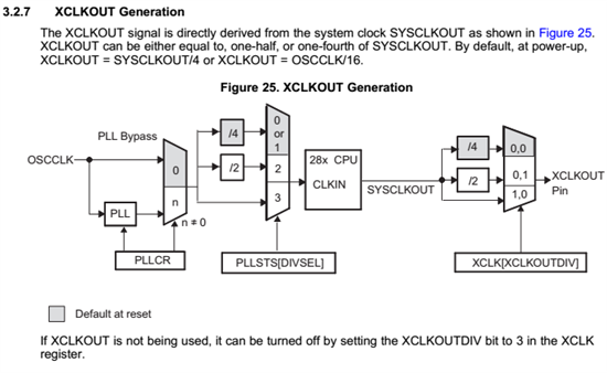
    The best way to confirm the CPU speed is to output the SYSCLK onto the XCLKOUT pin.

    -Tommy

  • I can confirm that the XCLKOUT using a divider of 1 gives a 60MHz output as expected.

    Do you have any other ideas where the slowness could come from? I see that the processor is pipelined with 8 stages. The 134 nanoseconds adds up assuming the 512 consecutive MOVs are not pipelined for whatever reason.

    However, the original problem with ADC still remains. If the input to the ADC is 60MHz and it needs to do four conversions in a chain, each taking 7 clock cycles, then generating an interrupt which simply acknowledges the interrupt and sets a flag, how does that take 7 microseconds?!

    Is there a way to check more precisely how long the ADC works?

  • Honestly a lot of things seem to be slow, in a weird way. Here is a simplified version of what I'm doing:

    while (1)
    {
        ((GPIO_Obj *)handles.gpio)->GPACLEAR = (uint32_t)1 << GPIO_Number_16; /* set pin to zero */
        control_loop();
        /* called 64 times to measure time and reduce error from GPIO set */
        ((GPIO_Obj *)handles.gpio)->GPASET = (uint32_t)1 << GPIO_Number_16;   /* set pin to one */
    }

    Inside the control loop I have:

    param = calc_control_param();  /* reads from ADC */
    output_pwms(param);

    The details of which are unimportant.

    Now inside output_pwms, if I don't do anything, I get an execution time of about 660us (for 64 calls to the control_loop function). Let's assume that value is sane. Now inside output_pwms, if I simply add:

    clk->PCLKCR0 &= (~CLK_PCLKCR0_TBCLKSYNC_BITS);
    clk->PCLKCR0 |= CLK_PCLKCR0_TBCLKSYNC_BITS;

    Since changing PWM parameters requires disabling the sync clock first and then enabling it again, then I suddenly get about 1420us execution time (for 64 calls to the control_loop function). In other words, simply disabling and enabling the TBCLKSYNC bits of the clock is taking about 12us?!

    (Note: EALLOW is set outside the loop, since EALLOW and EDIS pair itself was also introducing a non-significant delay (about 3us))

    I would greatly appreciate any help, as the microcontroller is behaving bizarrely slow.

  • As yet another example, inside the output_pwms function I set many settings for the PWMs, including:

    pwm->AQCTLA |= PWM_ActionQual_Clear << 8;
    pwm->AQCTLB |= PWM_ActionQual_Clear << 8;

    which happens 4 times (once for each PWM). If I simply comment these two lines (regardless of the incorrectness of the result), the execution time of the function is reduced by about 2.5us. Does that make sense? Each of those lines translates to 3 instructions. Is 24 instructions, pipelined with other instructions (which seems to be especially improved by the optimizer as those instructions are interleaved with others) supposed to take 2.5us when the CPU runs at 60MHz?

  • Shahbaz,

    One thing to keep in mind here is that the ACQPS value is only the S/H stage.  An additional 13 ADC clocks are required to convert the S/H voltage into a digital value.

    Settings in the ADCCTL2 register can also vary the ADC timings.  You can refer to the timing diagrams in the datasheet or ADC reference guide for this.

    -Tommy

  • Are you executing out of RAM or FLASH?

  • Thanks for the hints.

    Actually you are right, I'm executing from Flash. I changed the title of the discussion to better reflect the content.

    Speaking of RAM, I had done the following (in the very least, for DSP28x_usDelay (from DELAY_US), which executes from RAM):

    /* defined by the linker */
    extern Uint16 RamfuncsLoadStart;
    extern Uint16 RamfuncsLoadEnd;
    extern Uint16 RamfuncsRunStart;

        /* later in code */

        /* copy time critical code and flash setup/write code to RAM */

        memcpy((void *)RamfuncsRunStart, (void *)RamfuncsLoadStart, RamfuncsLoadEnd-RamfuncsLoadEnd);

        /* setup flash waitstates */
        FLASH_setup(handles.flash);

    Noting that this in the examples is surrounded by #ifdef _FLASH, which I'm not clear on whether it's automatically defined or not. Either way, executing this results in an RTOSINT interrupt, and the micro halts at this point. The relative part from the linker .cmd file is the following inside SECTIONS:

       ramfuncs            : LOAD = FLASHA,
                             RUN = PRAML0,
                             LOAD_START(_RamfuncsLoadStart),
                             LOAD_END(_RamfuncsLoadEnd),
                             RUN_START(_RamfuncsRunStart),
                             PAGE = 0

    I'm using the f28026.cmd file from the control suite (version 210). The runtime support library is selected automatically by code composer. I'm also linking to f2802x_common/lib/driverlib.lib from the control suite.

    Following the assembly, the problem is in FLASH_setup, which in turn calls FLASH_setStandbyWaitCount, which ends up at the marked point (giving a bit of context too):

                FLASH_setup, RamfuncsRunStart:
    008000:   49D5        TBIT         *+XAR5[2], #0x9
    008001:   6544        SB           68, LEQ
    326         FLASH_setStandbyWaitCount(flashHandle, 0x01FF);
    008002:   D7D2        MOVB         AR7, #0xd2
    008003:   78E2        MOV          *+XAR2[4], AR0
    008004:   5539        CMP          AH, @0x39
    008005:   6082        SB           -126, NEQ       <<<---------- OFFENDING INSTRUCTION
    328         FLASH_setActiveWaitCount(flashHandle, 0x01FF);

    End result is that the marked SB instruction jumps to a part of memory that is not mapped anywhere (address 007f87, which is 126 bytes before). It seems like it's trying to jump somewhere outside the function!

    Do you have any idea why? Am I configuring something incorrectly? Should I be using a different linker file, or link to a different library? Should I recompile the whole control suite library myself, so it would conform to my settings?

    Thank you for the continued support

  • Shahbaz,

    Would it be possible to do the initial debug and checkout in RAM only?  It will be easier confirm the performance expectations in RAM and then we can move on to the FLASH considerations after a baseline has been established.

    As far as the _FLASH variable goes, you can see this in the Project Properties -> Build -> C2000 Compiler -> Predefined Symbols -> [Flash Configuration] -> Pre-define NAME

    -Tommy

  • Tommy,

    I wish I could. As I mentioned, any attempt to run from RAM resulted in RTOSINT. Do you mind taking a look at my last post, checking whether there is something missing from the configuration?

    I am using CCS 5.5, and under Predefined Symbols, there is no such thing as Flash Configuration. Nonetheless, if the only effect is to define a _FLASH symbol, I don't have a problem with defining it myself. I suspected that perhaps there would be other modifications, the definition of the _FLASH symbol being a side effect it.

    Shahbaz

  • To clarify, I have the classic DEBUG and RELEASE configurations. I tried importing one of the example projects and I do see RAM and FLASH configuration in that one. How can I get those configurations for my own project too? I only see the F2802x_Headers_nonBIOS.cmd file in the example project. Looking at the settings, I don't see anything useful either (there are a lot of settings, so perhaps I'm missing).

    Did I perhaps create the wrong project type from the beginning?

  • Ok, I just tried executing a very small version of my program from RAM, using 28026_RAM_lnk.cmd instead of F28026.cmd, and I can confirm a significant increase in execution speed.

    Nevertheless, I need to obviously store the code in flash (not just for persistence, but also because it doesn't all fit in RAM). Back to the problem before, if I use F28026.cmd, and use memcpy to copy the functions to RAM (as I showed in a previous post above), calling anything on the RAM halts the CPU with RTOSINT.

    I found SPRA958H just now and I'll try to figure this out on my own. If not, I'll start another discussion.

    Thank you for your time

  • Are you able to build and load an existing ControlSUITE project into flash?  If so, it might be easier to just replace the code in an existing project with your own.

  • For future reference, I found my error:

    On my line:

    memcpy((void *)RamfuncsRunStart, (void *)RamfuncsLoadStart, RamfuncsLoadEnd-RamfuncsLoadEnd);

    Besides the fact that I should have done End-Start rather than End-End, I should have used the address of those variables, rather than their value, because the linker file binds those symbols to the first byte of the copy sections. I was under the impression that the linker binds them to the address of those locations. In other words:

    memcpy(&RamfuncsRunStart, &RamfuncsLoadStart, &RamfuncsLoadEnd - &RamfuncsLoadStart);

  • Glad to hear that you traced down the culprit.