This thread has been locked.

If you have a related question, please click the "Ask a related question" button in the top right corner. The newly created question will be automatically linked to this question.

Reading ADC in 320F28335 does not start from Zero

Hye

I am using TMS 320F28335 to control PMSM. I am facing ADC problem because when I connect ADC cable to ADC automatically reads the values round about 1820. When I activate the filter, it reads zero but then whatever analogue while I input, digital output remains almost zero i mean round about 20,30.

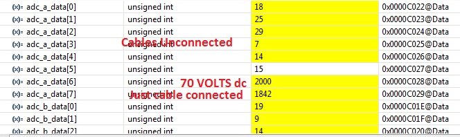
As in the figure below ADC without filter with just cable connected and no analogue input reads 1842, with 70 volts DC input it reads 2000 and rest of the values shown are all other ADCs without cables connected. I have selected internal voltage reference for ADC and the TMS320F28335 board is custom made.

How can I make ADC to read 0 at no analogue input and then increase digital value accordingly. 

Best Regards

Shahid Atiq

  • Hi Shahid,

    When no input is connected ie is left floating then you tend to get random values and that's exactly what you're observing.

    How can I make ADC to read 0 at no analogue input and then increase digital value accordingly.

    Try using a pull-down resistor.

    Regards,

    Gautam


  • Dear Gautam

    You are right that when ADC input is floating it reads random values. But when I connect Analogue input from Voltage or current sensor, ADC starts reading 1840 digital output. Because analogue input range of this ADC is from 0~3.3  volts and digital output resolution is 12 bit i.e when analogue input is zero digital output is zero and when analogue input is 3.3V digital output is 4095.  It means whenever i just connect the cable without any voltage or current at current or voltage sensor ADC reads about 1840 i.e 1.483 Volts.

    Note that cable that connects ADC and Voltage or current sensors contains four wires +15V, GND, -15V and Analogue signal. Can it be due to these voltage interference i.e +15V and -15 V required to drive voltage and current sensors with ADC?

    Best Regards

    Shahid

  • Hi Shahid,

    It is a little unclear exactly what you are connecting and sampling, but you should keep the following in mind:

    *The F28335 ADC is actually 0 to 3.0V range, not 0 to 3.3V.

    *Getting good ADC results may require a low source impedance.

    *Applying +/-15V to the ADC will cause permanent damage to the ADC.

    *The ADC may not resolve 0V as digital result 0 due to offset error.  We specify this error in the datasheet.