This thread has been locked.

If you have a related question, please click the "Ask a related question" button in the top right corner. The newly created question will be automatically linked to this question.

PFC implementation regarding spra902.pdf Application Report

Other Parts Discussed in Thread: CONTROLSUITE, TMS320F28027

Hi all,

I am implementing a PFC using a C2000 Launchpad, already have the system working to a fashion but I need to improve the algorithm, then increase the PWM and sampling frequency.  My original target was 60kHz, but due to me using C and not assembly, the max PWM rate is 25kHz.  This produces a very noisy current and input waveform (images below show the current traces).  The PI loops are not tuned fully either yet, but wanted to focus on the PWM frequency first.

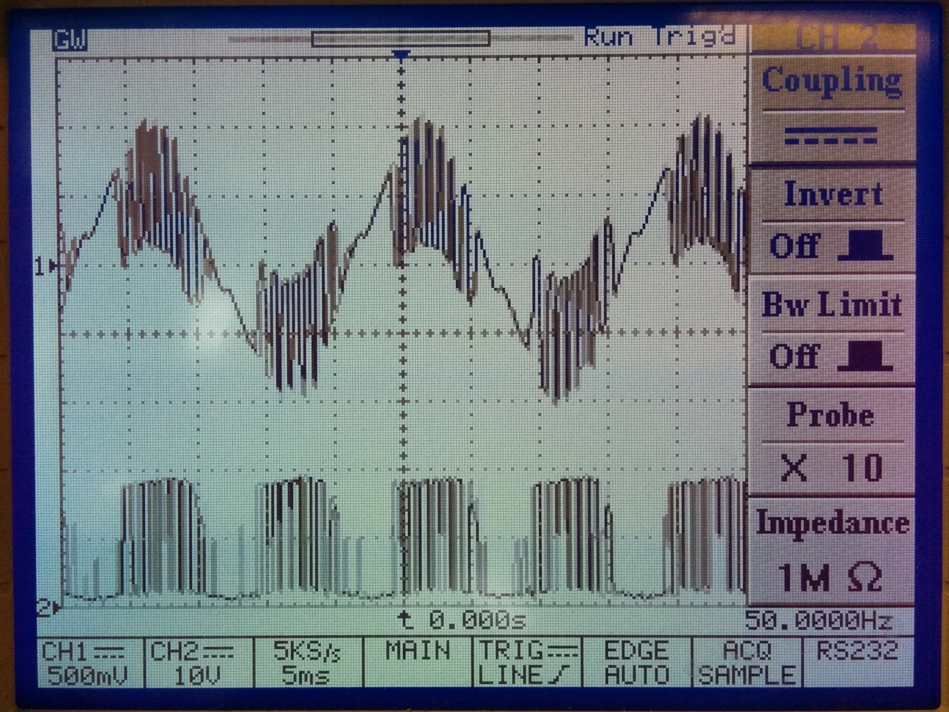
I am using various sources and on my third 3rd algorithm to see which works best, allowing me to increase the PWM and sampling rate.  Want to construct an algorithm from the spra902.pdf Application Note by Shamin Choudhury.  However I am having trouble understanding where 1 particular term is derived.  The equations are copied below, and from page 10 of the document, which can be found here

The term Usi is the one I am unsure about, as read the report I am struggling to see the difference between Ui(n) and Usi.  So unsure how Usi is derived?  

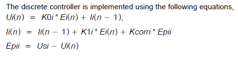
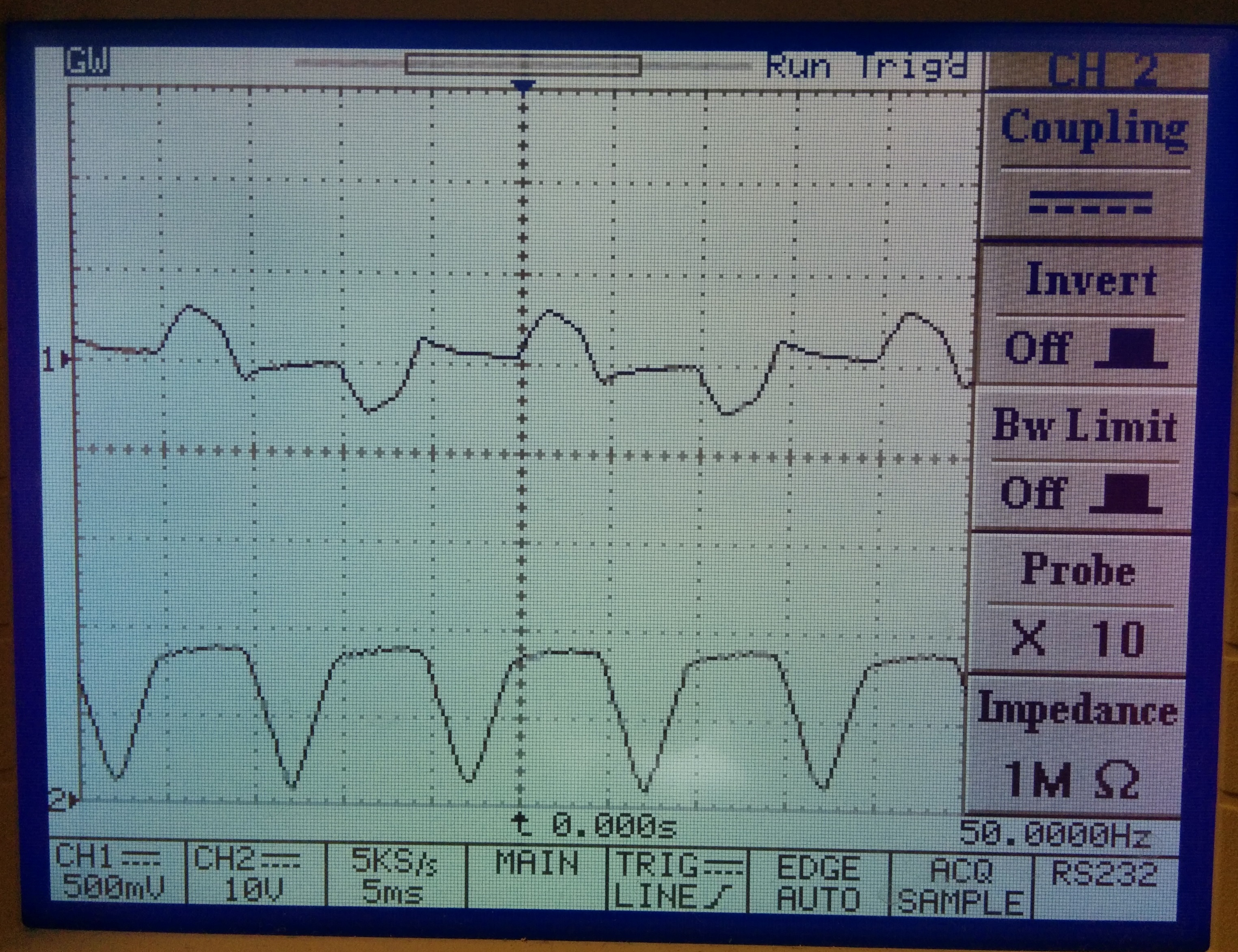
Images below: First one shows the start condition no PFC in operation and the second one shows the PFC in operation.  The current waveform (top) and the input voltage waveform after the bridge rectifier (bottom).  A basic current transformer and resistor was used to monitor the current, as no proper oscilloscope probe was to hand.

Thanks in advance,

Ant

  • Ant,

    Usi is the controller output after saturation. Ui(n) is the same controller output before saturation. Therefore Epii measures  the difference between the saturated and normal output. This difference is used with Kcorri to unwind the controller from its saturated state.

    We also released a PFC Evaluation kit last year. You can get the s/w and documentation by installing ControlSUITE from TI website. After you install controlSUITE, this PFC folder will be under ControlSUITE\development_kits\ILPFC_v1.0. You can also order the PFC kit from eStore.

    Shamim

  • Hi Shamim,

    Firstly thank you very much for your answer, and nice to know the Application Report author heard about my question.  I have to admit I have a fairly good understanding of the PFC operation now, but the control algorithm is proving difficult to implement, so hoping I can ask for a little more of your time?

    As per my previous post I am using the basic TMS320F28027 processor.  I have not used Q15 notation or Assembly, so I don't have the best implementation for a PFC.  I new nothing on the subject of PFC's 7 weeks ago, so would implement this differently in the future.  However I am quite sure I am close to having something that works, albeit a very noisy current waveform.

    I have all the rectified voltage samples and calculation of the average voltage working fine, as well as the a calculation for the line frequency.  The PWM frequency is now set to 24kHz, and I trigger an ADC read on every third event, this gives enough time to run the code inside the ADC interrupt without any overrun (checked this by polling a GPIO on/off to confirm stable timing).

    I am trying to develop a second PI control algorithm based directly off your application report, and have the following so far.  Bearing in mind I am not using Kcorri and relying on floats!  Therefore I am unsure how to implement Usi (if I can at all).

    	if (Slow_Start == 1)
    	{
    
    		Err_V = V_Ref - Vout_Volt;				// Ref voltage - Instantaneous Output Voltage
    		V_control = Kp_V * Err_V + Iv_nminus1;	// Proportional voltage constant * Voltage error + Iv_nminus1
    		Iv_n = Iv_nminus1 + (Ki_V * Samp_Freq) * V_control;	// Iv_nminus1 + (Integral voltage constant * Sampling Frequency=0.000125) * V_control
    
    		I_Ref = (V_control * Rect_Volt) / ( Vavg * Vavg);	// This is effectively A*B*C from the application report
    
    		Err_I = I_Ref - I_Rect;					// I_Ref - Instantaneous current sample
    		I_control = Kp_I * Err_I + Ii_nminus1;	// Proportional current constant * Current error + Ii_nminus1
    		Ii_n = Ii_nminus1 + (Ki_I * Samp_Freq) * I_control;	// Ii_nminus1 + Integral current constant * Sampling Frequency=0.000125) * I_control
    
    		Duty_Cycle = I_control * PWM_getCmpA(myPwm1); // I_control * latest duty cycle
    
    					// limiting for testing will extend limits as test progress
    					if (Duty_Cycle > 1800)
    					{Duty_Cycle = 1800;}
    					else if (Duty_Cycle < 400)
    					{Duty_Cycle = 400;}
    		
    		// interleaved design so 2 PWM's to update
    		EPwm1Regs.CMPA.half.CMPA = Duty_Cycle;	// Update PWM1
    		EPwm2Regs.CMPA.half.CMPA = Duty_Cycle;	// Update PWM2
    		
    		// Store values
    		Ii_nminus1 = Ii_n;
    		Iv_nminus1 = Iv_n;
    		
    		//d_nminus1 = I_control;
    
    	}	

    I have a 2nd algorithm which produces the oscilloscope traces shown in my previous post

    	if (Slow_Start == 1)
    	{
    
    	Err_V = V_Ref - Vout_Volt;
    	V_control = V_control_nminus1 + Kp_V * Err_V + (Ki_V * Samp_Freq - Kp_V) * Err_V_nminus1;
    	I_Ref = (V_control * Rect_Volt) / ( Vavg * Vavg);
    
    	if (I_Ref > 0.7)
    	{I_Ref = 0.7;}
    
    	Err_I = I_Ref - I_Rect;
    	d = d_nminus1 + Kp_I * Err_I + (Ki_I * Samp_Freq - Kp_I) * Err_I_nminus1;
    
    	Duty_Cycle = d * PWM_getCmpA(myPwm1);
    
    				if (Duty_Cycle > 2400)
    				{Duty_Cycle = 2400;}
    				else if (Duty_Cycle < 10)
    				{Duty_Cycle = 10;}
    
    	EPwm1Regs.CMPA.half.CMPA = Duty_Cycle;
    	EPwm2Regs.CMPA.half.CMPA = Duty_Cycle;
    
    	Err_V_nminus1 = Err_V;
    	Err_I_nminus1 = Err_I;
    	V_control_nminus1 = V_control;
    
    	d_nminus1 = d;
    
    	}

    I appreciate you are busy and understand if you don't have time to look into this further, will leave the post as unanswered for now and change it to answered after the weekend.

    Best regards,

    Ant

  • This is an old appnote. I would suggest that you use the other ILPFC kit information that I sent you and design a much improved PFC.

    Shamim