


Hi all,
Part of my code is supposed to do following:
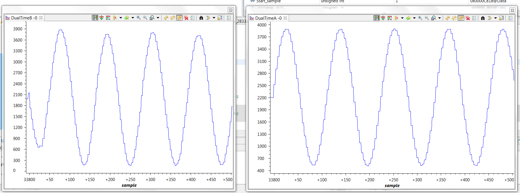
ADC is in continuous mode converting two channels at sample rate defined by EPWM2. DMA is using address of ADC mirror ADCRESULTn registers to move data to buffer ADCBufRaw[1080] : first 540 data are from ADCRESULT0, next 540 are from ADCRESULT1. Signal to ADC is sinusoidal burst of few periods - 100 to 20kHz freq range. The problem is that I get stepped sinusoidal form in buffer - few samples have the same value. Times between this hold ups are not constant. Graph of signal I get is shown below.
I tried modifying code for different ADC setup, read reference guides but found no answers. DMA setup is ok - i get correct data. Only DMA memory and buffer are allocated in RAML4 so processor doesn't collide with dma.
Relevant code is bellow:
ADC PART:
AdcRegs.ADCTRL1.bit.RESET = 1; // Reset the ADC
asm(" RPT #22 || NOP"); // Must wait for ADC reset to take effect
ADC_cal();
//--- Select the ADC reference
AdcRegs.ADCREFSEL.bit.REF_SEL = 0; // 0=internal, 1=external
AdcRegs.ADCTRL3.all = 0x00EC; // Power-up reference and main ADC, FCLK=2MSPS
DELAY_US(ADC_usDELAY);
AdcRegs.ADCMAXCONV.all = 0x0001;
AdcRegs.ADCCHSELSEQ1.bit.CONV00 = 0x3; // Setup ADCINA3 as 1st SEQ1 conv.
AdcRegs.ADCCHSELSEQ1.bit.CONV01 = 0x2; // Setup ADCINA2 as 2nd SEQ1 conv.
AdcRegs.ADCTRL1.all = 0x0010; //cascaded sequencer
AdcRegs.ADCTRL2.all = 0x0900; //INT_ENA_SEQ1=1, ePWM_SOCA_SEQ1=1
EPWM PART:
EALLOW;
SysCtrlRegs.PCLKCR0.bit.TBCLKSYNC = 0;
EDIS;
EPwm2Regs.TBCTL.bit.CTRMODE = 0x3; // Disable the timer
EPwm2Regs.TBCTL.all = 0xC033; // Configure timer control register
// bit 15-14 11: FREE/SOFT, 11 = ignore emulation suspend
// bit 13 0: PHSDIR, 0 = count down after sync event
// bit 12-10 000: CLKDIV, 000 => TBCLK = HSPCLK/1
// bit 9-7 000: HSPCLKDIV, 000 => HSPCLK = SYSCLKOUT/1
// bit 6 0: SWFSYNC, 0 = no software sync produced
// bit 5-4 11: SYNCOSEL, 11 = sync-out disabled
// bit 3 0: PRDLD, 0 = reload PRD on counter=0
// bit 2 0: PHSEN, 0 = phase control disabled
// bit 1-0 11: CTRMODE, 11 = timer stopped (disabled)
EPwm2Regs.TBCTR = 0x0000; // Clear timer counter
EPwm2Regs.TBPRD = 0x96; // Set timer period 150 MHz/1MHz -> 150
EPwm2Regs.TBPHS.half.TBPHS = 0x0000; // Set timer phase
EPwm2Regs.ETPS.all = 0x0100; // Configure SOCA
EPwm2Regs.ETSEL.all = 0x0A00; // Enable SOCA to ADC
EPwm2Regs.TBCTL.bit.CTRMODE = 0x0; // Enable the timer in count up mode
asm(" EALLOW"); // Enable EALLOW protected register access
SysCtrlRegs.PCLKCR0.bit.TBCLKSYNC = 1; // TBCLK to ePWM modules enabled
asm(" EDIS"); // Disable EALLOW protected register access
DMA PART:
#pragma DATA_SECTION(AdcBufRaw, "DMARAML4"); // USE different memory location - RAML5; others: 4,6,7 are used by FFT
Uint16 AdcBufRaw[1080]; // ADC raw data buffer allocation
DMAInitialize();
for (i=0; i<1080; i++) // clear DMA buffer
{
AdcBufRaw[i] = 0;
}
// Configure 1st DMA Channel
DMADest = &AdcBufRaw[0]; //Point DMA destination to the beginning of the array
DMASource = &AdcMirror.ADCRESULT0; //Point DMA source to ADC result register base
DMACH1AddrConfig(DMADest,DMASource);
DMACH1BurstConfig(1,1,540); //Burst 2 words, inc src address by 1, inc dest address by 540
DMACH1TransferConfig(539,0,0); //540 bursts per tranfer
DMACH1WrapConfig(0,0,0,1); //Wrap after 1 burst
DMACH1ModeConfig(DMA_SEQ1INT,PERINT_ENABLE,ONESHOT_DISABLE,CONT_DISABLE,SYNC_DISABLE,SYNC_SRC,
OVRFLOW_DISABLE,SIXTEEN_BIT,CHINT_END,CHINT_ENABLE);
interrupt void local_DINTCH1_ISR(void) // DMA Channel 1
{
DmaRegs.CH1.CONTROL.bit.PERINTCLR=1;
PieCtrlRegs.PIEACK.all = PIEACK_GROUP7;
}
Main while(1) loop containts function to run DMA at needed intervals
EALLOW;
DmaRegs.CH1.CONTROL.bit.RUN = 1;
EDIS;
BUFFERED SIGNAL LOOKS LIKE THIS (AT LOWER FREQUENCY-20kHz)
Any advice is welcome!! :)

