This thread has been locked.

If you have a related question, please click the "Ask a related question" button in the top right corner. The newly created question will be automatically linked to this question.

Problem related to MAX526 Dac connected to TMS320f2812

Other Parts Discussed in Thread: TMS320F2812

Hello,


I am currently using TMS320f2812 and on my custom board i have MAX526 DAC connected to it. The DAC is connected via the Xintf Zone 0 of my  f2812 (i.e. connected via the external interface bus). I dont clearly understand how to give the specific signals to my DAC. I know how to initialize the XINTF zone 0, but don't know how to give control signals like _LDAC, _CSLSB, _CSMSB .

I know you can give XWE signal(i.e is the write data signal ) but how to give the other signals.

Can you just give me a sample code of how to send these other control signals (the signals don't have to be the same as i mentioned). You can take any other DAC as an example.

Please help me out here.

Thank you in advance.

  • Rachit,

    I am moving this post to the C2000 forum to get you a response. 

  • Hi Rachit,

    Once you have the XINTF correctly setup, you can directly write (or read) XINTF zone 0 memory addresses (0x2000 to 0x3FFF) and these will be translated to writes(or reads) to the memory mapped locations on your DAC. e.g. if the DAC has some register called 'control register 1' at location 0x40 in its memory space, you can use the following c28x code to write to it:

    *((Uint16*)0x2040) = data;

    Obviously things will be much neater if you use # defines:

    #define DAC_CTRL_REG1 *((Uint16*)0x2040)

    so now

    DAC_CTRL_REG1 = data;

    If you need additional control other than the DAC memory mapped registers, you can control a GPIO directly:

    GpioDataRegs.GPADAT.bit.GPIO0 = 1;

    If this was say an enable signal, you could also # define this:

    #define DAC_ENABLE GpioDataRegs.GPADAT.bit.GPIO0 

    so now

    DAC_ENABLE = 1;

    Really once the XINTF is working and you have control of GPIOs (the GPIO initializations are working) you should be able to define everything in a headerfile.  Once this is done, you just need to figure out what commands to send, in what order to send them, and when to send them - this should be dictated by the DAC datasheet and your application needs and should be mostly decoupled from the XINTF/GPIO implementation details.

  • #define DAC_CTRL_REG1 *((Uint16*)0x2040)

    Doesn't  the address has to within the region defined by the .cmd file?

     XINTF       : origin = 0x000B20, length = 0x000020     /* external interface registers */

    So instead of selecting the address as 0x2040 i have to take 0x0B20 .

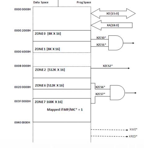
  • Ok, according to the above picture i have to give the values through the XD and it is between 0x0000 and 0x02000.

    So i cannot understand whether to give the data to Zone 0 or XD. (my dac is connected to zone 0).

    And how do you define the different zones in your .cmd file.

  • Zone 0 is 0x2000 to 0x3FFF in the C28x memory space.  If you write to the first location in this zone (0x2000) then the address lines will be 0x0000 and the data lines will be whatever you wrote.  If you write to the second location in the zone (0x2001) then the address lines will be 0x0001 and the data lines will be whatever you wrote.  Similar behavior occurs for the other zones, but they will active different CS signals as indicated in the above diagram.

    You don't give the values through XD, you just do a memory write like you would to any other memory location in the C28x memory hierarchy (like a peripheral control registers or any variable or array that you define in your program).  

    You could certainly also use the .cmd file to place specific variables at the desired locations, but I think for something like a DAC using # defines is probably easier.  

    Note that memory locations 0x0000 to 0x1FFF are not associated with the XINTF but instead with something else in the C28x memory map.  

  • But before writing the code we have to define the memory space for Zone 0 in the .cmd file

    Like in assembly code i saw this example and the guy wrote to define the memory regions as-

    DAC1       .set      0x3000
    DAC2       .set        0x3001
    DAC3       .set     0x3002
    DAC4       .set        0x3003

    and then he gave the value to the specific region by-

    OUT *(DAC3),@AL  

    thus giving the value to the memory region corresponding to DAC3.

    So how do i realize this in c.

    Do i just add this in my .cmd file-

     DAC1        : origin = 0x003000, length = 0x000001 
       DAC2        : origin = 0x003001, length = 0x000001   
       DAC3        : origin = 0x003002, length = 0x000001   
       DAC4        : origin = 0x003003, length = 0x000001    

  • I wrote this program-

    #include "DSP281x_Device.h"     // DSP281x Headerfile Include File   
    #include "DSP281x_Examples.h"   // DSP281x Examples Include File   


    #define DAC3  0x003002
    #define Ptr1        (( Uint16 *)DAC3)
    void Gpio_select(void);
    void InitSystem(void);

    void main()

    {
       
        InitSystem();
       InitXintf();//initialise timing strobe for R/W w.r.to zone
       Gpio_select();
       
       
      while(1)
      {
       GpioDataRegs.GPBTOGGLE.all=0x0040;  //giving low signal to _CSLSB so that DAC accepts 8 bit LSB data
       *Ptr1 = 0xff;
        GpioDataRegs.GPBTOGGLE.all=0x0040;        //giving high signal _CSLSB
        GpioDataRegs.GPBTOGGLE.all=0x0080;       //giving low signal to _CSMSB so that DAC accepts 4 bit MSB data
        *Ptr1 =0x2;
        GpioDataRegs.GPBTOGGLE.all=0x0080;       //giving high signal _CSMSB
        GpioDataRegs.GPFTOGGLE.all=0x0800;       //giving low signal to_LDAC
        }
        }


    But when i look at the memory map while excecuting this code , I am not getting the value at the 0x3002 location. There is some random value in it.

    Can you please point out the mistake in my code.


    Do we have to separately activate the zone 0 (do i have to make chip select statement go low in my code via the XA) or by adding the DSP28x_Xintf.c it is activated..

  • I am not sure if you can directly look at the XINTF locations in the memory browser; there isn't a local memory backed version of whatever you wrote on the device. I think you need to initiate a read to that XINTF memory location in your code and then store it to a variable, then look at the variable in the expressions window.  This assumes that your DAC allows read-back of the control registers that you wrote.  

    You need to enable the specific XINTF zones and set their specific timings and settings.  I think these should be in the InitXintf() funtion.

    In general, you will probably want to get an o'scope or logic analyzer to confirm if your commands are being transformed into the desired pin toggles.   

  • There was some code error. Thank you for your time.