This thread has been locked.

If you have a related question, please click the "Ask a related question" button in the top right corner. The newly created question will be automatically linked to this question.

Cannot reach max RPM

Other Parts Discussed in Thread: DRV8301, BOOSTXL-DRV8301, LAUNCHXL-F28027F, MOTORWARE, CONTROLSUITE, DRV8312, DRV8303

Hello Chris and InstaSPIN community,

CCS Version: 5.4.0.00091 

I am using a custom low inductance, 3 paired pole, 9.8V, BLDC motor with DRV8301-69M-KIT.  After reading every piece of literature and forum post I could find I am still unable to spin the motor at the rated 20krpm.  At this point in time I am able to hit right around 14krpm.  I have varied the USER_PWM_FREQ_kHz from 10 to 80 as well as tried increasing #define USER_MAX_VS_MAG_PU to 1.333, as in lab10.

I read that I may get poor results at a bus voltage of 9.8 due to ADC resolution.  Is there a method recommended for altering the board to solve this issue?

My goal is: Speed control from 300 rpm - 20krpm

The best results I could get so far are with the attached user.h file

Thanks in advance!

USER_PWM_FREQ_kHz = 25
USER_MAX_VS_MAG_PU = 1.0

7282.user.h

  • Chris,

    The source impedance of your resistor divider will be approximately 4.99k || 13.3k = 3.7k.  

    The RC time constant is about 1.1*sqrt((3.7k*5pF)^2 + (3.4k*1.6pF)^2) = 21.2ns.

    9.01*21.2ns = 191ns.  Compare this with minimum S+H duration of 7 ADCCLKs = 7*22.22ns = 155.5ns, so it may be a good idea to increase the S+H duration a little bit.

    9.01 was calculated as -ln(1/(2^13)) = settling to within 1/2LSBs.  This requirement can be relaxed based on your accuracy requirements.

    Alternately, you can add a charge-sharing capacitor after the resistor divider of around 2^(N+1)*Cs+h = 8192*1.6pF = 13.1nF.  This will allow the external capacitance to completely charge the internal S+H capacitor, ignoring the voltage divider source impedance. This will create a LP filter between the resistor divider and the charge sharing capacitor (-3dB around 3.3kHz), which may not be desirable.

    You can lower the resistor divider resistances to trade voltage divider static power dissipation against increased filter BW (or to lower the RC time constant when not using a charge-sharing capacitor).  

  • Thank you again Devin and Chris for your feedback.

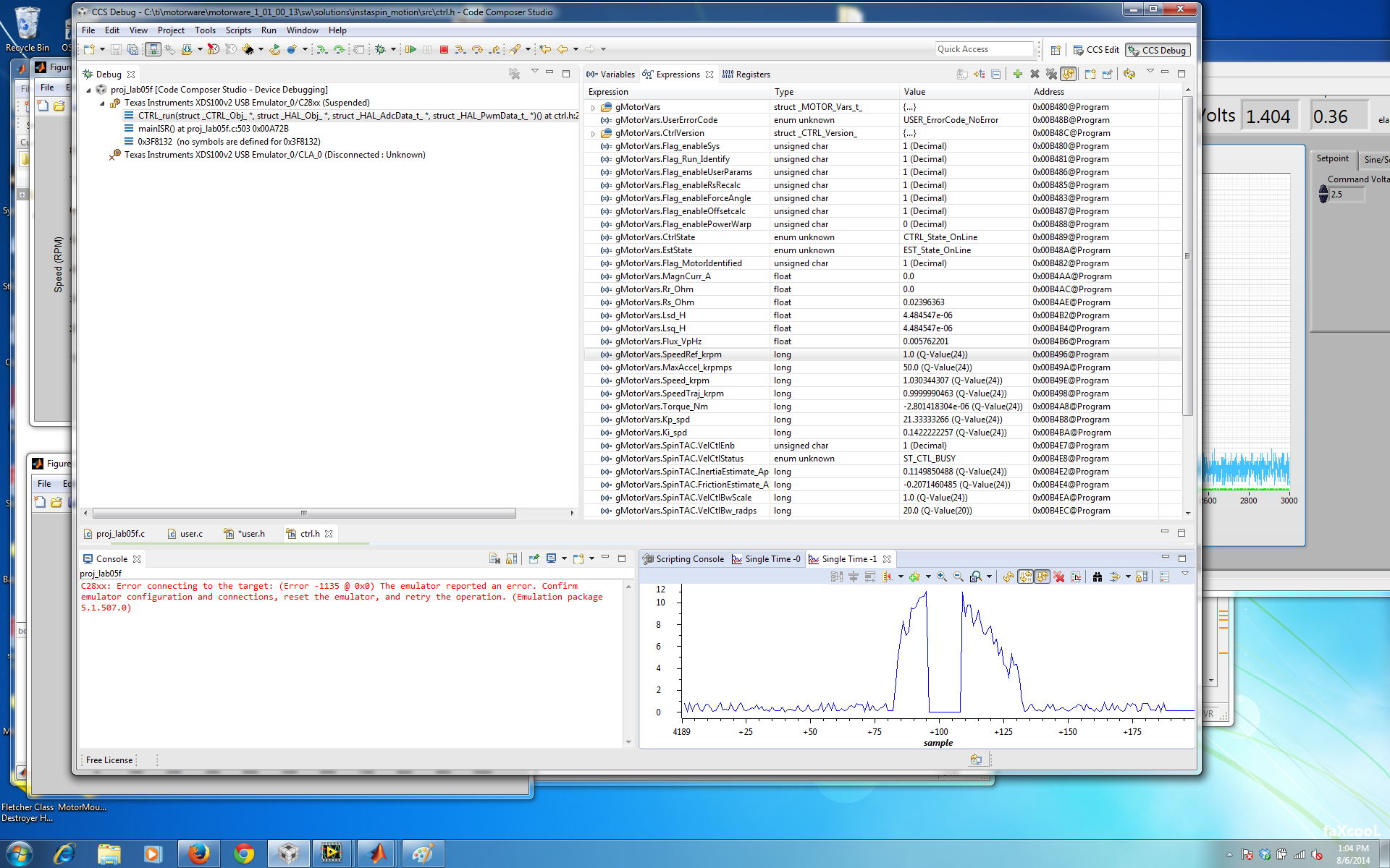
    I'm still not understanding why my Is_A current is set to zero when it becomes too high. Is this a saturation problem? My current sense resistor divider is scaled for +/-40 amps (see graph below).

    Also, I still can't explain why I'm able to run the dev kit PWM frequency anywhere from 30-90 kHz, but our custom motor controller only runs when at 90 kHz. I already replaced all of the dev kit current sense and voltage sense resistors to be equivalent in scale to my board, and I'm running essential the same code (except for difference in GPIO pin numbers).

    Any thoughts on these two issues?

  • We found a solution to the problem. Thank you for all your help along the way. It turned out that we need to reduce the sample delay from ADC_SocSampleDelay_9_cycles to only ADC_SocSampleDelay_7_cycles, and this fixed all our problems. We're now able to run at a lower PWM frequency, and the noise in the Vc (voltage sense for phase C) has been dramatically reduced. Please pass this information along to other developers, as I wouldn't have believed that changing the sample delay by 2 samples would have such a significant impact on performance.

    Best regards,

    Chris

  • very interesting. asking around the team and someone has recognized this before. We are going to do some more investigation. Thanks for posting your findings.