This thread has been locked.

If you have a related question, please click the "Ask a related question" button in the top right corner. The newly created question will be automatically linked to this question.

Strange behaviour on 28335 Dual Sequencer ADC

Other Parts Discussed in Thread: TMS320F28335

Hi

I'm using the  dual sequencer mode on TMS320F28335 ADC.

SOC is triggered by ePWM:

Sequencer1: SOCA from ePWM1 when CTR=PRD
Sequencer2: SOCB from ePWM2 when CTR=PRD

After EOC (end of conversion) an interrupt is triggered:

INT_SEQ1 for sequencer 1
INT_SEQ2 for sequencer 2

Because I want to use oversampling on SEQ1 I retrigger SEQ1 within INT_SEQ1

When I do this it corrupts INT_SEQ2 periodically which means that INT_SEQ2 is missed sometimes or occurs multiple times (a counter variable within INT_SEQ2 shows that INT_SEQ2 is called again when I reenable interrupts before ISR is finished).

If ePWM frequencies are exactly identical then there is no problem.
How is it possible that SEQ1 influences SEQ2 interrupt in this way?

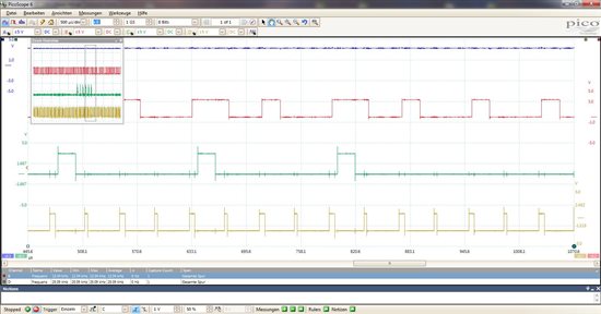
Attached you find a small program (CCS V5.5, Code Generation Tools V6.20.00) which shows the timing on three output pins. Also attached you find the actual timing output:

Blue: please ignore
Red: High within INT_SEQ2
Green: should never occurr: high within INT_SEQ2 if called a second time
Yellow: toggles each time INT_SEQ1 is called

Thanks in advance for our support!

Markus

2022.ADCTest.zip

  • Hi Markus,

    This is definitely strange behavior. 

    I am not able to successfully unzip your project.  Can you try just uploading the .c file?

    When the interrupts overlap, how do you handle prioritization? 

    I wonder if you can get the error to occur on every interrupt by running the two ePWMs at the same frequency, but slowly changing the phase difference in the watch window until the error occurs?

  • Hi Devin,


    I think I found the error and it definitely looks like a hardware bug.

    The error also occurrs when I write to any bit within ADCTRL2 Register inside EOC_SEQ1 interrupt.
    I have written to e.g. INT_MOD_SEQ1 the same value that I initialy configured this Register -> error occurs.

    Also if I write to e.g. rsvd bit (according to ADC documentation spru812a writing to reserved bits has no effect), again the error occurs. If I dont write to ADCTRL2 inside interrupt everythis is fine (no error).

    Next I tested if the compiler translates bit access (e.g. AdcRegs.ADCTRL2.bit.SOC_SEQ1 = 1) to an atomic instruction. It definitely does (uses OR instruction). The same assembly code is generated when I use the compliter intrinsic __or( (int *)&AdcRegs.ADCTRL2.all, 0x2000); So it is an atomic instruction.

    The behaviour can be explained if the bit access is internally split into a read/modify/write operation:

    case A:

    1) ePWM sets SOC_SEQ2 bit within ADCTRL2
    2) CPU reads ADCTRL2 (read part of writing to bit SOC_SEQ1)
    3) ADC module clears SOC_SEQ2 (conversion on sequencer 2 has started) 
    4) CPU modifies SOC_SEQ1 bit and writes back to ADCTRL2
    -> error, SOC_SEQ2 is set again and conversion on sequencer 2 is restarted after first conversion is complete.


    case B:

    1) CPU reads ADCTRL2 (read part of writing to bit SOC_SEQ1)
    2) ePWM sets SOC_SEQ2 bit within ADCTRL2
    3) CPU modifies SOC_SEQ1 bit and writes back to ADCTRL2
    -> error, SOC_SEQ2 is cleared before ADC has seen it -> conversion on sequencer 2 does not start.

    Attached you find a modified version of my program, including a workround which worked to me:
    As ePWM2 triggers SOC_SEQ2 when CTR=PRD, I check if CTR of ePWM2 is near PRD and if so, I wait until CTR is enough away from PRD. Then I set AdcRegs.ADCTRL2.bit.SOC_SEQ1 = 1 > error does not occur anymore.

    #include <stdlib.h>
    #include "DSP2833x_EPwm_defines.h"
    #include "DSP2833x_Device.h"
    #include "System.h"


    //******************************************************************************
    // SYMBOLIC CONSTANTS
    //******************************************************************************
    
    #define ADC_SAMPLE_COUNT_SEQ1    2
    
    //******************************************************************************
    // TYPES
    //******************************************************************************
    
    
    //******************************************************************************
    // IMPORTS
    //******************************************************************************
    
    //------------------------------------------------------------------------------
    // Procedures
    //------------------------------------------------------------------------------
    
    
    //------------------------------------------------------------------------------
    // Variables
    //------------------------------------------------------------------------------
    
    //******************************************************************************
    // VARIABLES
    //******************************************************************************
    
    volatile unsigned short us_NumberOfSamples = ADC_SAMPLE_COUNT_SEQ1 - 1;
    volatile unsigned short us_NestedInterruptTestCounter = 0;
    volatile unsigned short us_NestedInterruptCounter = 0;
    
    //******************************************************************************
    // PROCEDURES
    //******************************************************************************
    
    //------------------------------------------------------------------------------
    // ISRPhantom:
    //------------------------------------------------------------------------------
    
    interrupt void ISRPhantom(void)
    {
      asm(" ESTOP0 ");
    }
    
    //------------------------------------------------------------------------------
    // ISR_EOC_SEQ1: Interrupt
    //------------------------------------------------------------------------------
    
    interrupt void ISR_EOC_SEQ1(void)
    {
      // acknowledge interrupt in PIE
      PieCtrlRegs.PIEACK.all = PIEACK_GROUP1;
    
      // clear interrupt flag
      AdcRegs.ADCST.bit.INT_SEQ1_CLR = 1;
    
      if (us_NumberOfSamples > 0)
      {
        Uint16 criticalLimit = EPwm2Regs.TBPRD - 13;
        us_NumberOfSamples--;
        while (EPwm2Regs.TBCTR > criticalLimit); // wait until it's save to write to ADCTRL2
        AdcRegs.ADCTRL2.bit.SOC_SEQ1 = 1;
      }
      else
      {
        us_NumberOfSamples = ADC_SAMPLE_COUNT_SEQ1 - 1;
      }
    
      // Debug-Pin 4
      GpioDataRegs.GPCTOGGLE.bit.GPIO67=1;
    
    }
    
    
    //------------------------------------------------------------------------------
    // ISR_EOC_SEQ2: Interrupt
    //------------------------------------------------------------------------------
    
    interrupt void ISR_EOC_SEQ2(void)
    {
      // acknowledge interrupt in PIE
      PieCtrlRegs.PIEACK.all = PIEACK_GROUP1;
    
      // clear interrupt flag
      AdcRegs.ADCST.bit.INT_SEQ2_CLR = 1;
    
      us_NestedInterruptTestCounter++;
      if (us_NestedInterruptTestCounter == 1)
      {
        // Debug-Pin 2
        GpioDataRegs.GPASET.bit.GPIO20=1;
      }
      else if (us_NestedInterruptTestCounter == 2)
      {
        us_NestedInterruptCounter++;
        // Debug-Pin 3
        GpioDataRegs.GPCSET.bit.GPIO66=1;
      }
    
      IER = M_INT1;
    
      EINT;
    
      // simulation of other tasks
      usDelay(20);
    
      DINT;
    
      if (us_NestedInterruptTestCounter == 2)
      {
        // Debug-Pin 3
        GpioDataRegs.GPCCLEAR.bit.GPIO66=1;
      }
      else if (us_NestedInterruptTestCounter == 1)
      {
        // Debug-Pin 2
        GpioDataRegs.GPACLEAR.bit.GPIO20=1;
      }
      us_NestedInterruptTestCounter--;
    }
    
    
    //*******************************************************************************
    // MAIN
    //*******************************************************************************
    
    void main(void)
    {
      InitSystem();
    
      EINT;
    }


    #include <stdlib.h>
    #include "DSP2833x_EPwm_defines.h"
    #include "DSP2833x_Device.h"
    #include "System.h"
    
    
    //******************************************************************************
    // SYMBOLIC CONSTANTS
    //******************************************************************************
    
    
    //******************************************************************************
    // TYPES
    //******************************************************************************
    
    //******************************************************************************
    // IMPORTS
    //******************************************************************************
    
    //------------------------------------------------------------------------------
    // Procedures
    //------------------------------------------------------------------------------
    
    extern void ADC_cal(void);
    
    extern interrupt void ISRPhantom(void);
    extern interrupt void ISR_EOC_SEQ1(void);
    extern interrupt void ISR_EOC_SEQ2(void);
    
    //------------------------------------------------------------------------------
    // Variables
    //------------------------------------------------------------------------------
    
    // Diese Variablen werden vom Linker generiert (siehe cmd Datei)
    extern Uint16 RamfuncsLoadStart;
    extern Uint16 RamfuncsLoadEnd;
    extern Uint16 RamfuncsRunStart;
    
    //------------------------------------------------------------------------------
    // Constants
    //------------------------------------------------------------------------------
    
    const struct PIE_VECT_TABLE PieVectTableInit = {
    
      ISRPhantom,   // 0  Reserved space
      ISRPhantom,   // 1  Reserved space
      ISRPhantom,   // 2  Reserved space
      ISRPhantom,   // 3  Reserved space
      ISRPhantom,   // 4  Reserved space
      ISRPhantom,   // 5  Reserved space
      ISRPhantom,   // 6  Reserved space
      ISRPhantom,   // 7  Reserved space
      ISRPhantom,   // 8  Reserved space
      ISRPhantom,   // 9  Reserved space
      ISRPhantom,   // 10 Reserved space
      ISRPhantom,   // 11 Reserved space
      ISRPhantom,   // 12 Reserved space
    
      // Non-Peripheral Interrupts
      ISRPhantom,   // XINT13 or CPU-Timer 1
      ISRPhantom,   // XINT14 or CPU-Timer 2
      ISRPhantom,   // Datalogging interrupt
      ISRPhantom,   // RTOS interrupt
      ISRPhantom,   // Emulation interrupt
      ISRPhantom,   // Non-maskable interrupt
      ISRPhantom,   // Illegal operation TRAP
      ISRPhantom,   // User Defined trap 1
      ISRPhantom,   // User Defined trap 2
      ISRPhantom,   // User Defined trap 3
      ISRPhantom,   // User Defined trap 4
      ISRPhantom,   // User Defined trap 5
      ISRPhantom,   // User Defined trap 6
      ISRPhantom,   // User Defined trap 7
      ISRPhantom,   // User Defined trap 8
      ISRPhantom,   // User Defined trap 9
      ISRPhantom,   // User Defined trap 10
      ISRPhantom,   // User Defined trap 11
      ISRPhantom,   // User Defined trap 12
    
      // Group 1 PIE Vectors
      ISR_EOC_SEQ1, // 1.1 SEQ1INT
      ISR_EOC_SEQ2, // 1.2 SEQ2INT
      ISRPhantom,   // 1.3 Reserved
      ISRPhantom,   // 1.4 XINT-1
      ISRPhantom,   // 1.5 XINT-2
      ISRPhantom,   // 1.6 ADCINT
      ISRPhantom,   // 1.7 Timer 0
      ISRPhantom,   // 1.8 WAKEINT (WD, Low Power)
    
      // Group 2 PIE Vectors
      ISRPhantom,   // 2.1 EPWM-1 Trip Zone
      ISRPhantom,   // 2.2 EPWM-2 Trip Zone
      ISRPhantom,   // 2.3 EPWM-3 Trip Zone
      ISRPhantom,   // 2.4 EPWM-4 Trip Zone
      ISRPhantom,   // 2.5 EPWM-5 Trip Zone
      ISRPhantom,   // 2.6 EPWM-6 Trip Zone
      ISRPhantom,   // 2.7 Reserved
      ISRPhantom,   // 2.8 Reserved
          
      // Group 3 PIE Vectors
      ISRPhantom,   // 3.1 EPWM-1 Interrupt
      ISRPhantom,   // 3.2 EPWM-2 Interrupt
      ISRPhantom,   // 3.3 EPWM-3 Interrupt
      ISRPhantom,   // 3.4 EPWM-4 Interrupt
      ISRPhantom,   // 3.5 EPWM-5 Interrupt
      ISRPhantom,   // 3.6 EPWM-6 Interrupt
      ISRPhantom,   // 3.7 Reserved
      ISRPhantom,   // 3.8 Reserved
          
      // Group 4 PIE Vectors
      ISRPhantom,   // 4.1 ECAP-1
      ISRPhantom,   // 4.2 ECAP-2
      ISRPhantom,   // 4.3 ECAP-3
      ISRPhantom,   // 4.4 ECAP-4
      ISRPhantom,   // 4.5 ECAP-5
      ISRPhantom,   // 4.6 ECAP-6
      ISRPhantom,   // 4.7 Reserved
      ISRPhantom,   // 4.8 Reserved
          
      // Group 5 PIE Vectors
      ISRPhantom,   // 5.1 EQEP-1
      ISRPhantom,   // 5.2 EQEP-2
      ISRPhantom,   // 5.3 Reserved
      ISRPhantom,   // 5.4 Reserved
      ISRPhantom,   // 5.5 Reserved
      ISRPhantom,   // 5.6 Reserved
      ISRPhantom,   // 5.7 Reserved
      ISRPhantom,   // 5.8 Reserved
    
    
      // Group 6 PIE Vectors
      ISRPhantom,   // 6.1 SPIRXINTA
      ISRPhantom,   // 6.2 SPITXINTA
      ISRPhantom,   // 6.3 MRINTB (McBSP-B, SPI-B)
      ISRPhantom,   // 6.4 MXINTB (McBSP-B, SPI-B)
      ISRPhantom,   // 6.5 MRINTA (McBSP-A)
      ISRPhantom,   // 6.6 MTINTA (McBSP-A)
      ISRPhantom,   // 6.7 Reserved
      ISRPhantom,   // 6.8 Reserved
          
      // Group 7 PIE Vectors
      ISRPhantom,   // 7.1 DINTCH1 (DMA)
      ISRPhantom,   // 7.2 DINTCH2 (DMA)
      ISRPhantom,   // 7.3 DINTCH3 (DMA)
      ISRPhantom,   // 7.4 DINTCH4 (DMA)
      ISRPhantom,   // 7.5 DINTCH5 (DMA)
      ISRPhantom,   // 7.6 DINTCH6 (DMA)
      ISRPhantom,   // 7.7 Reserved
      ISRPhantom,   // 7.8 Reserved
    
      // Group 8 PIE Vectors
      ISRPhantom,   // 8.1 I2CINT1A
      ISRPhantom,   // 8.2 I2CINT2A
      ISRPhantom,   // 8.3 Reserved
      ISRPhantom,   // 8.4 Reserved
      ISRPhantom,   // 8.5 SCIRXINTC
      ISRPhantom,   // 8.6 SCITXINTC
      ISRPhantom,   // 8.7 Reserved
      ISRPhantom,   // 8.8 Reserved
          
      // Group 9 PIE Vectors
      ISRPhantom,   // 9.1 SCIRXINTA
      ISRPhantom,   // 9.2 SCITXINTA
      ISRPhantom,   // 9.3 SCIRXINTB
      ISRPhantom,   // 9.4 SCITXINTB
      ISRPhantom,   // 9.5 ECAN0INTA
      ISRPhantom,   // 9.6 ECAN1INTA
      ISRPhantom,   // 9.7 ECAN0INTB
      ISRPhantom,   // 9.8 ECAN1INTB
          
      // Group 10 PIE Vectors
      ISRPhantom,   // 10.1 Reserved
      ISRPhantom,   // 10.2 Reserved
      ISRPhantom,   // 10.3 Reserved
      ISRPhantom,   // 10.4 Reserved
      ISRPhantom,   // 10.5 Reserved
      ISRPhantom,   // 10.6 Reserved
      ISRPhantom,   // 10.7 Reserved
      ISRPhantom,   // 10.8 Reserved
      
      // Group 11 PIE Vectors
      ISRPhantom,   // 11.1 Reserved
      ISRPhantom,   // 11.2 Reserved
      ISRPhantom,   // 11.3 Reserved
      ISRPhantom,   // 11.4 Reserved
      ISRPhantom,   // 11.5 Reserved
      ISRPhantom,   // 11.6 Reserved
      ISRPhantom,   // 11.7 Reserved
      ISRPhantom,   // 11.8 Reserved
            
      // Group 12 PIE Vectors
      ISRPhantom,   // 12.1 XINT3
      ISRPhantom,   // 12.2 XINT4
      ISRPhantom,   // 12.3 XINT5
      ISRPhantom,   // 12.4 XINT6
      ISRPhantom,   // 12.5 XINT7
      ISRPhantom,   // 12.6 Reserved
      ISRPhantom,   // 12.7 LVF, Latched overflow  (FPU)
      ISRPhantom,   // 12.8 LUF, Latched underflow (FPU) 
    };
    
    
    //******************************************************************************
    // VARIABLES
    //******************************************************************************
    
    //******************************************************************************
    // CONSTANTS
    //******************************************************************************
    
    //******************************************************************************
    // PROCEDURES
    //******************************************************************************
    
    //---------------------------------------------------------------------------
    // MemCopy:
    //---------------------------------------------------------------------------
    
    void MemCopy(Uint16 *SourceAddr, Uint16* SourceEndAddr, Uint16* DestAddr)
    {
      while(SourceAddr < SourceEndAddr)
      { 
        *DestAddr++ = *SourceAddr++;
      }
      return;
    }
    
    
    //---------------------------------------------------------------------------
    // InitPll: configures PLL to these values:
    //          - Oscillator Clock=30MHz
    //          - CPUCLK=SYSCLKOUT=150MHz
    //          --> PLLCR=0x0A
    //          --> DIVSEL=2
    //
    //          CPUCLK= (Oscillator*PLLCR)/DIVSEL    
    //---------------------------------------------------------------------------
    
    void InitPll(void)
    {
      // Pr�fen ob PLL nicht im Limp Modus l�uft
      if (SysCtrlRegs.PLLSTS.bit.MCLKSTS != 0)
      {
        // Clock von extern ist nicht vorhanden
        asm(" ESTOP0");
      }
    
      // DIVSEL muss zuerst auf 0 gesetzt werden, bevor PLLCR ge�ndert wird
      if (SysCtrlRegs.PLLSTS.bit.DIVSEL != 0)
      {
        EALLOW;
        SysCtrlRegs.PLLSTS.bit.DIVSEL = 0;
        EDIS;
      }
       
      // PLLCR �ndern
      if (SysCtrlRegs.PLLCR.bit.DIV != 0x0A)
      {       
        EALLOW;
        // Missing Clock Detect Logik ausschalten
        SysCtrlRegs.PLLSTS.bit.MCLKOFF = 1;
        SysCtrlRegs.PLLCR.bit.DIV = 0x0A;
        EDIS;
                
        // Warten, bis PLL eingerastet ist (locked)
        while(SysCtrlRegs.PLLSTS.bit.PLLLOCKS != 1) 
        {}
        // Missing Clock Detect Logik einschalten
        EALLOW;
        SysCtrlRegs.PLLSTS.bit.MCLKOFF = 0;
        EDIS;
      }
    
      //DIVSEL auf 2 setzen ((OSCCLK*PLLCR)/2
      EALLOW;
      SysCtrlRegs.PLLSTS.bit.DIVSEL = 2;
      EDIS;
    
    }
    
    
    //--------------------------------------------------------------------------
    // InitPeripheralClocks:
    //---------------------------------------------------------------------------
    
    void InitPeripheralClocks(void)
    {
      EALLOW;
    
      // High-Speed Clock=SYSCLKOUT/6 (25MHz@150MHz)
      // Low-Speed Clock=SYSCLKOUT/2  (75MHz)
      SysCtrlRegs.HISPCP.all = 0x0003;
      SysCtrlRegs.LOSPCP.all = 0x0001;
    
      SysCtrlRegs.PCLKCR0.bit.ADCENCLK = 1;    // ADC
    
      // ADC_cal function copies ADC calibration values from OPT into registers ADCREFSEL und ADCCOFFTRIM
      // ADC-Clock must be enabled before ADC_cal() is called!
      
      ADC_cal();
    
      SysCtrlRegs.PCLKCR0.bit.I2CAENCLK = 0;   // I2C
      SysCtrlRegs.PCLKCR0.bit.SCIAENCLK = 0;   // SCI-A
      SysCtrlRegs.PCLKCR0.bit.SCIBENCLK = 0;   // SCI-B
      SysCtrlRegs.PCLKCR0.bit.SCICENCLK = 0;   // SCI-C
      SysCtrlRegs.PCLKCR0.bit.SPIAENCLK = 0;   // SPI-A
      SysCtrlRegs.PCLKCR0.bit.MCBSPAENCLK = 0; // McBSP-A
      SysCtrlRegs.PCLKCR0.bit.MCBSPBENCLK = 0; // McBSP-B
      SysCtrlRegs.PCLKCR0.bit.ECANAENCLK=0;    // eCAN-A
      SysCtrlRegs.PCLKCR0.bit.ECANBENCLK=0;    // eCAN-B
    
      SysCtrlRegs.PCLKCR0.bit.TBCLKSYNC = 0;   // Disable TBCLK within the ePWM
      SysCtrlRegs.PCLKCR1.bit.EPWM1ENCLK = 1;  // ePWM1
      SysCtrlRegs.PCLKCR1.bit.EPWM2ENCLK = 1;  // ePWM2
      SysCtrlRegs.PCLKCR1.bit.EPWM3ENCLK = 1;  // ePWM3
      SysCtrlRegs.PCLKCR1.bit.EPWM4ENCLK = 1;  // ePWM4
      SysCtrlRegs.PCLKCR1.bit.EPWM5ENCLK = 0;  // ePWM5
      SysCtrlRegs.PCLKCR1.bit.EPWM6ENCLK = 0;  // ePWM6
      SysCtrlRegs.PCLKCR0.bit.TBCLKSYNC = 1;   // Enable TBCLK within the ePWM
    
      SysCtrlRegs.PCLKCR1.bit.ECAP3ENCLK = 0;  // eCAP3
      SysCtrlRegs.PCLKCR1.bit.ECAP4ENCLK = 0;  // eCAP4
      SysCtrlRegs.PCLKCR1.bit.ECAP5ENCLK = 0;  // eCAP5
      SysCtrlRegs.PCLKCR1.bit.ECAP6ENCLK = 0;  // eCAP6
      SysCtrlRegs.PCLKCR1.bit.ECAP1ENCLK = 0;  // eCAP1
      SysCtrlRegs.PCLKCR1.bit.ECAP2ENCLK = 0;  // eCAP2
      SysCtrlRegs.PCLKCR1.bit.EQEP1ENCLK = 0;  // eQEP1
      SysCtrlRegs.PCLKCR1.bit.EQEP2ENCLK = 0;  // eQEP2
    
      SysCtrlRegs.PCLKCR3.bit.CPUTIMER0ENCLK = 0; // CPU Timer 0
      SysCtrlRegs.PCLKCR3.bit.CPUTIMER1ENCLK = 0; // CPU Timer 1
      SysCtrlRegs.PCLKCR3.bit.CPUTIMER2ENCLK = 0; // CPU Timer 2
    
      SysCtrlRegs.PCLKCR3.bit.DMAENCLK = 0;       // DMA Clock
      SysCtrlRegs.PCLKCR3.bit.GPIOINENCLK = 1;    // GPIO input clock
    
      // Sequenz um XCLKOUT auszuschalten
      SysCtrlRegs.PCLKCR3.bit.XINTFENCLK = 1;     // XTIMCLK
      XintfRegs.XINTCNF2.bit.CLKOFF = 1;          // XCLKOUT ausschalten (nur m�glich, wenn XTIMCLK ein)
      SysCtrlRegs.PCLKCR3.bit.XINTFENCLK = 0;     // XTIMCLK
    
      // synchronisation of all ePWM clocks
      // TBCLKSYNC must be set to 1 again after ePWM configuration
      SysCtrlRegs.PCLKCR0.bit.TBCLKSYNC = 0; 
    
      EDIS;
    }
    
    
    //---------------------------------------------------------------------------
    // InitFlash: Initialises Flash Control Registers
    //            Attention: must be executed from internal RAM!
    //---------------------------------------------------------------------------
    #pragma CODE_SECTION(InitFlash, "ramfuncs");
    
    void InitFlash(void)
    {
       EALLOW;
       // enable flash pipeline mode for faster code execution
       FlashRegs.FOPT.bit.ENPIPE = 1;
       
       // Attention: Waitstates are calculated for SYSCLKOUT=150MHz!
    
       // set flash timing according to TI documentation SPRS439
       FlashRegs.FBANKWAIT.bit.PAGEWAIT = 5;
       FlashRegs.FBANKWAIT.bit.RANDWAIT = 5;
       FlashRegs.FOTPWAIT.bit.OTPWAIT = 8;
       
       // only use default values for these registers!
       FlashRegs.FSTDBYWAIT.bit.STDBYWAIT = 0x01FF;
       FlashRegs.FACTIVEWAIT.bit.ACTIVEWAIT = 0x01FF;
       EDIS;
    
       // ensure code pipeline is empty before additional code is executed
       asm(" RPT #7 || NOP");
    } 
    
    
    //---------------------------------------------------------------------------
    // InitPieCtrl:
    //---------------------------------------------------------------------------
    
    void InitPieCtrl(void)
    {
      // disable PIE (Peripheral Interrupt Extension)
      PieCtrlRegs.PIECTRL.bit.ENPIE=0;
    
      // configure PIE Interrupt Enable register
      // Group 1
      PieCtrlRegs.PIEIER1.all=0;
      PieCtrlRegs.PIEIER1.bit.INTx1=1; // enable EOC_SEQ1 (end of conversion interrupt of AD sequencer 1)
      PieCtrlRegs.PIEIER1.bit.INTx2=1; // enable EOC_SEQ2 (end of conversion interrupt of AD sequencer 2)
    
      // Group 2
      PieCtrlRegs.PIEIER2.all=0;
    
      // Group 3
      PieCtrlRegs.PIEIER3.all=0;
      
      // Group 4
      PieCtrlRegs.PIEIER4.all=0;
    
      // Group 5
      PieCtrlRegs.PIEIER5.all=0;
    
      // Group 6
      PieCtrlRegs.PIEIER6.all=0;
    
      // Group 7
      PieCtrlRegs.PIEIER7.all=0;
    
      // Group 8
      PieCtrlRegs.PIEIER8.all=0;
    
      // Group 9
      PieCtrlRegs.PIEIER9.all=0;
    
      // Group 10
      PieCtrlRegs.PIEIER10.all=0;
    
      // Group 11
      PieCtrlRegs.PIEIER11.all=0;
    
      // Group 12
      PieCtrlRegs.PIEIER12.all=0;
    
      // clear all PIE Interrupt flags
      PieCtrlRegs.PIEIFR1.all=0;
      PieCtrlRegs.PIEIFR2.all=0;
      PieCtrlRegs.PIEIFR3.all=0;
      PieCtrlRegs.PIEIFR4.all=0;
      PieCtrlRegs.PIEIFR5.all=0;
      PieCtrlRegs.PIEIFR6.all=0;
      PieCtrlRegs.PIEIFR7.all=0;
      PieCtrlRegs.PIEIFR8.all=0;
      PieCtrlRegs.PIEIFR9.all=0;
      PieCtrlRegs.PIEIFR10.all=0;
      PieCtrlRegs.PIEIFR11.all=0;
      PieCtrlRegs.PIEIFR12.all=0;
    
    }
    
    
    //---------------------------------------------------------------------------
    // InitPieVectTable:
    //---------------------------------------------------------------------------
    
    void InitPieVectTable(void)
    {
      int16 i;
      Uint32 *Source = (void *) &PieVectTableInit;
      Uint32 *Dest = (void *) &PieVectTable;
        
      EALLOW; 
      for(i=0; i < 128; i++)
        *Dest++ = *Source++;
      EDIS;
    
      // enable PIE (Peripheral Interrupt Extension)
      PieCtrlRegs.PIECTRL.bit.ENPIE = 1;
    }
    
    
    //---------------------------------------------------------------------------
    // InitIO: configures GPIO for interrupt timing analysis
    //---------------------------------------------------------------------------
    
    void InitIO(void)
    {
      EALLOW;
    
      // Debug_Out1
      GpioCtrlRegs.GPAMUX2.bit.GPIO18  = 0;    // 0=GPIO,  1=SPICLK-A,  2=SCITX-B,  3=CANRX-A
      GpioCtrlRegs.GPAQSEL2.bit.GPIO18 = 0;    // 0=Sync, 1=Sync 3x, 2=Sync 6x, 3=Async
      GpioCtrlRegs.GPAPUD.bit.GPIO18   = 1;    // 0=Pullup enabled,  1=Pullup disabled
      GpioDataRegs.GPACLEAR.bit.GPIO18 = 1;    // Clear Output
      GpioCtrlRegs.GPADIR.bit.GPIO18   = 1;    // 0=Input, 1=Output
    
      // Debug_Out2
      GpioCtrlRegs.GPAMUX2.bit.GPIO20  = 0;    // 0=GPIO,  1=EQEPA-1,   2=MDX-A,    3=CANTX-B
      GpioCtrlRegs.GPAQSEL2.bit.GPIO20 = 0;    // 0=Sync, 1=Sync 3x, 2=Sync 6x, 3=Async
      GpioCtrlRegs.GPAPUD.bit.GPIO20   = 1;    // 0=Pullup enabled,  1=Pullup disabled
      GpioDataRegs.GPACLEAR.bit.GPIO20 = 1;    // Clear Output
      GpioCtrlRegs.GPADIR.bit.GPIO20   = 1;    // 0=Input, 1=Output
    
      // DebugOut3
      GpioCtrlRegs.GPCMUX1.bit.GPIO66  = 0;    // 0=GPIO,  1=GPIO,  2=XD13,  3=XD13
      GpioCtrlRegs.GPCPUD.bit.GPIO66   = 1;    // 0=Pullup enabled,  1=Pullup disabled
      GpioDataRegs.GPCCLEAR.bit.GPIO66 = 1;    // Clear Output
      GpioCtrlRegs.GPCDIR.bit.GPIO66   = 1;    // 0=Input, 1=Output
    
      // DebugOut4
      GpioCtrlRegs.GPCMUX1.bit.GPIO67  = 0;    // 0=GPIO,  1=GPIO,  2=XD12,  3=XD12
      GpioCtrlRegs.GPCPUD.bit.GPIO67   = 1;    // 0=Pullup enabled,  1=Pullup disabled
      GpioDataRegs.GPCCLEAR.bit.GPIO67 = 1;    // Clear Output
      GpioCtrlRegs.GPCDIR.bit.GPIO67   = 1;    // 0=Input, 1=Output
    
      EDIS;
    }
    
    //---------------------------------------------------------------------------
    // InitPWM:
    //---------------------------------------------------------------------------
    
    void InitPWM(void)
    {
      EALLOW;
    
      // Timebase (TB)
      EPwm1Regs.TBPRD=7500;
      EPwm1Regs.TBPHS.half.TBPHS=0;
      EPwm1Regs.TBCTL.bit.CTRMODE=TB_COUNT_UPDOWN;
      EPwm1Regs.TBCTL.bit.PHSEN=TB_DISABLE;
      EPwm1Regs.TBCTL.bit.PRDLD=TB_SHADOW;
      EPwm1Regs.TBCTL.bit.SYNCOSEL=TB_SYNC_DISABLE;
      EPwm1Regs.TBCTL.bit.CLKDIV=TB_DIV1;
      EPwm1Regs.TBCTL.bit.HSPCLKDIV=TB_DIV1;
      EPwm1Regs.TBCTL.bit.FREE_SOFT=0;
      EPwm1Regs.TBCTR = 0;
    
      // EPWM1 triggers SOC_SEQA
      EPwm1Regs.ETSEL.bit.SOCASEL=ET_CTR_PRD;
      EPwm1Regs.ETPS.bit.SOCAPRD=ET_1ST;
      EPwm1Regs.ETCLR.bit.SOCA=1;
      EPwm1Regs.ETSEL.bit.SOCAEN=1;
    
    
      // Timebase (TB)
      EPwm2Regs.TBPRD=7501;
      EPwm2Regs.TBPHS.half.TBPHS=0;
      EPwm2Regs.TBCTL.bit.CTRMODE=TB_COUNT_UPDOWN;
      EPwm2Regs.TBCTL.bit.PHSEN=TB_DISABLE;
      EPwm2Regs.TBCTL.bit.PRDLD=TB_SHADOW;
      EPwm2Regs.TBCTL.bit.SYNCOSEL=TB_SYNC_DISABLE;
      EPwm2Regs.TBCTL.bit.CLKDIV=TB_DIV1;
      EPwm2Regs.TBCTL.bit.HSPCLKDIV=TB_DIV1;
      EPwm2Regs.TBCTL.bit.FREE_SOFT=0;
      EPwm2Regs.TBCTR = 0;
    
      // EPWM2 triggers SOC_SEQB
      EPwm2Regs.ETSEL.bit.SOCBSEL=ET_CTR_PRD; //ET_CTR_ZERO;
      EPwm2Regs.ETPS.bit.SOCBPRD=ET_1ST;
      EPwm2Regs.ETCLR.bit.SOCB=1;
      EPwm2Regs.ETSEL.bit.SOCBEN=1;
    
      // synchronisation of clocks of all ePWM modules
      SysCtrlRegs.PCLKCR0.bit.TBCLKSYNC = 1;
    
      EDIS;
    }
    
    
    //---------------------------------------------------------------------------
    // InitADC: - Start/Stop Mode
    //          - Dual Sequenzer Mode
    //          - No Simultaneous Sampling Mode
    //          - Internal Referenc used
    //          - EOCA Interrupt SEQA
    //          - EOCB Interrupt SEQB
    //          - ADCCLK=HSPCLK=25MHz
    //          - Sample & Hold Time: 8 x ADCCLK Periods
    //---------------------------------------------------------------------------
    
    void InitADC(void)
    {
      // ADCCLK=HSPCLK=25MHz (max)
      AdcRegs.ADCTRL3.bit.ADCCLKPS=0;
    
      // enable reference
      AdcRegs.ADCTRL3.bit.ADCBGRFDN=3;
    
      // enable ADC
      AdcRegs.ADCTRL3.bit.ADCPWDN=1;
    
      // wait 5ms
      usDelay(5000);
    
      // Sampling time=8 x ADCCLK Periods
      AdcRegs.ADCTRL1.bit.ACQ_PS=7;
    
      // Dual Sequenzer Mode
      AdcRegs.ADCTRL1.bit.SEQ_CASC=0;
    
      // Start/Stop Mode
      AdcRegs.ADCTRL1.bit.CONT_RUN=0;
    
      // number of conversions (both sequencer with 8 conversions each)
      AdcRegs.ADCMAXCONV.bit.MAX_CONV1=7;
      AdcRegs.ADCMAXCONV.bit.MAX_CONV2=7;
      
      AdcRegs.ADCCHSELSEQ1.bit.CONV00=0;  // ADCINA0
      AdcRegs.ADCCHSELSEQ1.bit.CONV01=1;  // ADCINA1
      AdcRegs.ADCCHSELSEQ1.bit.CONV02=2;  // ADCINA2
      AdcRegs.ADCCHSELSEQ1.bit.CONV03=3;  // ADCINA3
      AdcRegs.ADCCHSELSEQ2.bit.CONV04=4;  // ADCINA4
      AdcRegs.ADCCHSELSEQ2.bit.CONV05=5;  // ADCINA5
      AdcRegs.ADCCHSELSEQ2.bit.CONV06=6;  // ADCINA6
      AdcRegs.ADCCHSELSEQ2.bit.CONV07=7;  // ADCINA7
      
      AdcRegs.ADCCHSELSEQ3.bit.CONV08=8;  // ADCINB0
      AdcRegs.ADCCHSELSEQ3.bit.CONV09=9;  // ADCINB1
      AdcRegs.ADCCHSELSEQ3.bit.CONV10=10; // ADCINB2
      AdcRegs.ADCCHSELSEQ3.bit.CONV11=11; // ADCINB3
      AdcRegs.ADCCHSELSEQ4.bit.CONV12=12; // ADCINB4
      AdcRegs.ADCCHSELSEQ4.bit.CONV13=13; // ADCINB5
      AdcRegs.ADCCHSELSEQ4.bit.CONV14=14; // ADCINB6
      AdcRegs.ADCCHSELSEQ4.bit.CONV15=15; // ADCINB7
    
      // clear SOC flags
      AdcRegs.ADCTRL2.bit.SOC_SEQ1=0;
      AdcRegs.ADCTRL2.bit.SOC_SEQ2=0;
     
      AdcRegs.ADCTRL2.bit.EPWM_SOCA_SEQ1=1; // start sequenzer1 by SOCA
      AdcRegs.ADCTRL2.bit.INT_ENA_SEQ1=1;   // enable Seq1 interrupt
      
      AdcRegs.ADCTRL2.bit.EPWM_SOCB_SEQ2=1; // start sequenzer2 by SOCB
      AdcRegs.ADCTRL2.bit.INT_ENA_SEQ2=1;   // enable Seq2 interrupt
    
    }
    
    
    //------------------------------------------------------------------------------
    // InitSystem:
    //------------------------------------------------------------------------------
    
    void InitSystem(void)
    {
      // config PLL (Oscillator Clock=30MHz, CPUCLK=SYSCLKOUT=150MHz)
      InitPll();
    
      // enable/disable clocks of individual peripheral modules
      InitPeripheralClocks();
    
      // copy code to RAM which needs to run in RAM
      MemCopy(&RamfuncsLoadStart, &RamfuncsLoadEnd, &RamfuncsRunStart);
    
      // must be executed in RAM!
      InitFlash();
    
      // configures all GPIO
      InitIO();
    
      // dsiable interrupts globally
      DINT;
       
      // init Peripheral Interrupt Extension
      InitPieCtrl();
    
      // disable and clear all interrupts
      IER = 0x0000;
      IFR = 0x0000;
    
      // init interrupt vector table
      InitPieVectTable();
    
      // init AD converter
      InitADC();
    
      // init ePWM Module
      InitPWM();
    
      // Enable group 1 (end of conversion interrupts from both sequencer 1 and 2)
      IER = M_INT1;
    }
    
    8103.System.h

    Could you confirm that this is a hardware bug which should appear in the errata?

    Best regards
    Markus

  • Markus,

    I will attempt to duplicate this behavior.

  • Hi Devin

    How far did you get in analysing this behavior?

    Regards
    Markus

  • Hi Markus,

    No progress to report, but this is certainly being tracked and should be completed in the next few days.

  • Hi Markus,

    I am still working on this.  So far I have determined:

    You can't set or clear specific bits in a register without a read-modify-write operation.  If you look at the OR operation in the CPU and instruction set reference guide (SPRU430E page 6-263) note that it specifies that it performs a read-modify-write operation.  Even though the effective number of cycles is 1, this is after pipelining.  The read of the memory occurs in R2 pipeline phase, while the write-back after ORing occurs one cycle after the W phase (page 4-2 describes the pipeline).  This leaves multiple cycles during which the OR operation is non-atomic. The CPU has write protection mechanisms, but these do not apply to registers being set indirectly (page 4-16).

    Because of the above, I can understand how SEQ2 would get converted twice: The register description for SOC_SEQ2 field says that if the sequencer is idle and the bit is cleared that "The bit is set and cleared".  If this means that the SOC_SEQ2 bit reads back 1 for one or more cycles, the CPU could read this as part of a read-modify-write in the R2 phase, the sequencer could then start and the bit is cleared in the next cycle, and then later the CPU writes back '1' causing another sequence to be pending.  I need to confirm this behavior, but I don't think this would require an erratum.

    I don't yet have an explanation for why the trigger would be missed.  My two ideas are that if 0 is written at the same time the trigger arrives, then the trigger is missed based on how the HW arbitrates this.  Otherwise, if SOC_SEQ2 reads back 1 for more than 1 cycles (perhaps because the HW doesn't clear this bit until the next ADCCLK edge) then if the CPU writes back 0 during this time and clears the bit the sequence will be missed.  I think the first mechanism would require an erratum, but the second may not.

    I will keep investigating this.  

  • Hi Devin

    Thanks for your progress report.

    My opinion is that regardless of how the behaviour can be explained, if there is no way to tell in advance how many times the sequencer starts after writeing to SOC_SEQ2 this is a bug (regardless if it's by design or not).

    What would be the official approach to start the seqencer exactly once?

    Markus