This thread has been locked.

If you have a related question, please click the "Ask a related question" button in the top right corner. The newly created question will be automatically linked to this question.

SPI communication between two F28069 Control Sticks

Other Parts Discussed in Thread: CONTROLSUITE

Hi

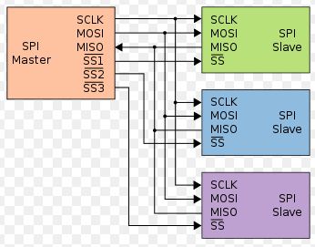
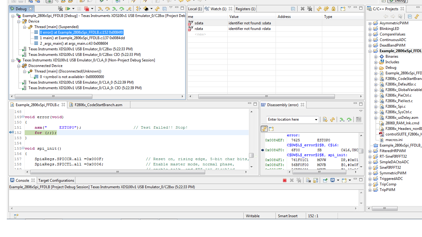
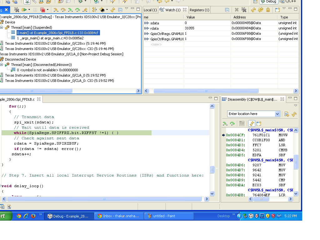
Kindly help me with SPI communication between two DSP F28069 control sticks on urgent basis.

I initially started with CAN but it is not possible with the control sticks and i have only three days left to establish communication between two control sticks.

I wish to send data through SPI of one DSP to SPI of another DSP n if possible display it on the terminal.

Thanking you in advance

Sneha

  • Hi Sneha,

    I initially started with CAN but it is not possible with the control sticks and i have only three days left to establish communication between two control sticks.

    Yup got to know that. I thought as you're planning to use eCAN you might be having the transceivers ready :)

    I wish to send data through SPI of one DSP to SPI of another DSP n if possible display it on the terminal.

    No problem, here's its much simpler: you can directly connect the SPISOMI, SPISIMO, SPICLK and SPISTEA lines to accordingly. For eg.

    Refer spi_loopback or spi_loopback_interrupts examples for quick implementations as times running! They can be found here:

    C:\ti\controlSUITE\device_support\f2806x\v136\F2806x_examples_ccsv5\spi_loopback

    Regards,

    Gautam

  • Hi Sneha,

    I initially started with CAN but it is not possible with the control sticks and i have only three days left to establish communication between two control sticks.

    I got to know that from your previous post. I pre-assumed that you might be having transceivers as you wanted to work on eCAN peripheral... Anyways:

    I wish to send data through SPI of one DSP to SPI of another DSP n if possible display it on the terminal.

    This is much simpler, no need of any hardware. You can connect your two boards in this fashion: (just an example)

    Also, refer the SPI based examples spi_loopback & spi_loopback_interrupts that can be found here:

    C:\ti\controlSUITE\device_support\f2806x\v136\F2806x_examples_ccsv5\spi_loopback

    This will help you in quick implementation and also don't forget to refer the SPI documentation for steps necessary.

    Regards,

    Gautam

  • Thank you Gautam..

    I am going through the given examples only...

  • Hi

    I have gone through the example codes.Now as per my understanding for communication between two control sticks:

    1.In SPICCR to keep the SPIBLK=0 i.e loopback disabled.

    2. In SPICTL changing bit 2 to 0/1 for slave/master dsps respectively.

    3. No use of SPI-B only using SPI-A in both DSPs with GPIO pins 16,17,18,19

    4. Enabling the transmission part in Master Dsp and recieving part in Slave DSPs.

    Please correct me if I am wrong.I have made the respective changes in programs for master/slave dsp's and got no error while debugging.

    Now should i proceed with their connections?

    How can we get a data transmitted such that it can be displayed on the terminal by slave DSP.

    Thank you

  • Now should i proceed with their connections?

    How can we get a data transmitted such that it can be displayed on the terminal by slave DSP.

    Yup, do proceed. You can check out the transmit and receive data registers of SPIA peripheral in Global variables (watch windows during debug session). No need to display the same on hyperterminal for now.

    Regards,

    Gautam

  • Hi Gautam

    I tried doing the implementation.The conncetions done were:

    Header pin 20(Master) to Pin 20(Slave),i.e SPISOMIA

    Header pin 24(Master) to Pin 24(Slave),i.e SPISIMOA

    Header pin 25(Master) to Pin 25(Slave),i.e SPISTEA

    Header pin 29(Master) to Pin 29(Slave),i.e SPICLKA

    But as i m running the program for master its haults in between and do not recognize sdata/rdata...... and for slave it shows changes only in sdata.

    The register values for spia registers are also not same..

    MASTER-

    #include "DSP28x_Project.h" // Device Headerfile and Examples Include File

    // Prototype statements for functions found within this file.
    // interrupt void ISRTimer2(void);
    void delay_loop(void);
    void spi_xmit(Uint16 a);
    void spi_fifo_init(void);
    void spi_init(void);
    void error(void);

    void main(void)
    {
    Uint16 sdata; // send data
    Uint16 rdata; // received data

    InitSysCtrl();


    InitSpiaGpio();


    DINT;


    InitPieCtrl();

    // Disable CPU interrupts and clear all CPU interrupt flags:
    IER = 0x0000;
    IFR = 0x0000;


    InitPieVectTable();


    spi_fifo_init(); // Initialize the Spi FIFO
    spi_init(); // init SPI


    sdata = 0x0000;
    for(;;)
    {
    // Transmit data
    spi_xmit(sdata);
    // Wait until data is received
    while(SpiaRegs.SPIFFRX.bit.RXFFST !=1) { }
    // Check against sent data
    rdata = SpiaRegs.SPIRXBUF;
    if(rdata != sdata) error();
    sdata++;
    }
    }

    // Step 7. Insert all local Interrupt Service Routines (ISRs) and functions here:

    void delay_loop()
    {
    long i;
    for (i = 0; i < 1000000; i++) {}
    }

    void error(void)
    {
    asm(" ESTOP0"); // Test failed!! Stop!
    for (;;);
    }

    void spi_init()
    {
    SpiaRegs.SPICCR.all =0x000F; // Reset on, rising edge, 16-bit char bits,loopback disabled
    SpiaRegs.SPICTL.all =0x0006; // Enable master mode, normal phase,
    // enable talk, and SPI int disabled.
    SpiaRegs.SPIBRR =0x007F;
    SpiaRegs.SPICCR.all =0x008F; // Relinquish SPI from Reset
    SpiaRegs.SPIPRI.bit.FREE = 1; // Set so breakpoints don't disturb xmission
    }

    void spi_xmit(Uint16 a)
    {
    SpiaRegs.SPITXBUF=a;
    }

    void spi_fifo_init()
    {
    // Initialize SPI FIFO registers
    SpiaRegs.SPIFFTX.all=0xE040;
    // SpiaRegs.SPIFFRX.all=0x2044;
    SpiaRegs.SPIFFCT.all=0x0;
    }

    SLAVE

    #include "DSP28x_Project.h"     // Device Headerfile and Examples Include File

    // Prototype statements for functions found within this file.
    // interrupt void ISRTimer2(void);
    void delay_loop(void);
    //void spi_xmit(Uint16 a);
    void spi_fifo_init(void);
    void spi_init(void);
    void error(void);

    void main(void)
    {
      Uint16 sdata;  // send data
       Uint16 rdata;  // received data
       

       InitSysCtrl();

       InitSpiaGpio();


       DINT;


       InitPieCtrl();

    // Disable CPU interrupts and clear all CPU interrupt flags:
       IER = 0x0000;
       IFR = 0x0000;
       

       InitPieVectTable();
        

       spi_fifo_init();      // Initialize the Spi FIFO
       spi_init();          // init SPI

    // Step 5. User specific code:
    // Interrupts are not used in this example. 
       sdata = 0x0000;                            
       for(;;)
       {    
         // Transmit data
      //   spi_xmit(sdata);
         // Wait until data is received
         while(SpiaRegs.SPIFFRX.bit.RXFFST !=1) { }             
         // Check against sent data
         rdata = SpiaRegs.SPIRXBUF;                
         if(rdata != sdata) error();
         sdata++;
       }
    }     

    // Step 7. Insert all local Interrupt Service Routines (ISRs) and functions here:    

    void delay_loop()
    {
        long      i;
        for (i = 0; i < 1000000; i++) {}
    }

    void error(void)
    {
        asm("     ESTOP0");                        // Test failed!! Stop!
        for (;;);
    }

    void spi_init()
    {    
        SpiaRegs.SPICCR.all =0x000F;                 // Reset on, rising edge, 16-bit char bits  
        SpiaRegs.SPICTL.all =0x0002;                 // Enable master mode, normal phase,
                                                     // enable talk, and SPI int disabled.
        SpiaRegs.SPIBRR =0x007F;                                    
        SpiaRegs.SPICCR.all =0x00F;                 // Relinquish SPI from Reset   
        SpiaRegs.SPIPRI.bit.FREE = 1;                // Set so breakpoints don't disturb xmission
    }

    //void spi_xmit(Uint16 a)
    //{
    //    SpiaRegs.SPITXBUF=a;
    //}    

    void spi_fifo_init()                                        
    {
    // Initialize SPI FIFO registers
     //   SpiaRegs.SPIFFTX.all=0xE040;
        SpiaRegs.SPIFFRX.all=0x2044;
        SpiaRegs.SPIFFCT.all=0x0;
    }  

  • Hi

    After checking the signals on DSO for master i am getting output for clock only and negative voltage for MOSI and positive for MISO..

    when i check out the watch varibales

    rdata= identifier not found

    sdata=once it will be 0 and some other time it would be identifier not found..

    Kindly help.

  • HI Gautam

    I am trying to that SPI interface for two f28069 control sticks..I changed the SPICCR to loopback disabled and SPICTL 1/0 for master and slave dsp's.
    But I am not getting anything when i check the watch variable for sdata it is zero at times and at times identifier is not found..while rdata has some value...
    So,am not sure whether this is true or not?

    when is check the spi_loopback example on DSO and make the changes in it for loopback disabled mode,it does nt give the required waveforms..Actaully changing any of the bits of SPICCR results in this..

    Kindly reply ,I am stuck here for last two days.

    thanks

  • Sneha, sorry for the late reply. I would like you to check this pdf:

    http://academic.cankaya.edu.tr/~yuriy/Lessons/Module7.pdf

    Regards,

    Gautam

  • Hi

    I have gone through the pdf and the required changes have already been implemented and I am still facing the issues.see the attached screenshots

    1

    this one is for master...sdata..rdata not recognised...

    SpiaRegs.SPICCR.all =0x000F; // Reset on, rising edge, 5-bit char bits,loopback disabled
    SpiaRegs.SPICTL.all =0x0006; // Enable master mode, normal phase,
    // enable talk, and SPI int disabled.
    SpiaRegs.SPIBRR =0x007F;
    SpiaRegs.SPICCR.all =0x008F; // Relinquish SPI from Reset
    SpiaRegs.SPIPRI.bit.FREE = 1; // Set so breakpoints don't disturb xmission
    }

    and for slave:

    SpiaRegs.SPICCR.all =0x000F;              // Reset on, rising edge, 16-bit char bits  
    SpiaRegs.SPICTL.all =0x0002;          // Enable master mode, normal phase,
                                                     // enable talk, and SPI int disabled.
    //SpiaRegs.SPIBRR =0x007F;
        SpiaRegs.SPICCR.all =0x008F;          // Relinquish SPI from Reset   
        SpiaRegs.SPIPRI.bit.FREE = 1; 
  • HI

    I have again checked up the Pdf.

    1. In the Pdf SPICCR.4= reserved while in datasheet i.e SPRU18 SPICCR.4= SPILBK...which one is correct?

    2. The program works only when SPILBK is enabled..But as I am communicating between two control sticks,shouldn't it be disabled?

    3. Is it required to set SPIDAT,SPISTS register in the program or is it automatically taken?

    I am working on SPI_loopback without interrupt.

    thank you

  • Hi,

    1. In the Pdf SPICCR.4= reserved while in datasheet i.e SPRU18 SPICCR.4= SPILBK...which one is correct?

    Refer only SPRU18D for configurations, the pdf that I've attached above is a generic one and is only for reference.

    2. The program works only when SPILBK is enabled..But as I am communicating between two control sticks,shouldn't it be disabled?

    You've to disable this mode for communication between 2 controlSticks ie SPILBK = 0;

    3. Is it required to set SPIDAT,SPISTS register in the program or is it automatically taken?

    SPIDAT is the register where the data is loaded and you don't have to worry about that it will be taken care by the library. As for SPISTS, here's an example:

    Uint16 data;
    Uint16 dummy;
    SpiaRegs.SPICTL.bit.TALK = 1;                                            // Enable Transmit path
    SpiaRegs.SPITXBUF = data;                                                 // Master transmits data
    while(SpiaRegs.SPISTS.bit.INT_FLAG !=1) {}                    // Waits until data rx’d
    dummy = SpiaRegs.SPIRXBUF;                                          // Clears junk data from itself
                                                                                                        // bc it rx’d same data tx’d

    Regards,

    Gautam

  • Hi

    Thanks Gautam . It solved my previous problem.

    Now when I test the slave or even when i connect both the control sticks, Send data bit i.e. sdata is always zero,recieve data bit i.e. rdata changes but gets fixed at a certain number and does not change afterwards...

  • Gautam,

    the website you refered to is not authorized to publish that material. The officlal material, including the SPI - chapter can be found and downloaded here:

    http://e2e.ti.com/group/universityprogram/educators/w/wiki/2037.teaching-roms.aspx

    and especially for C2000: http://e2e.ti.com/group/universityprogram/educators/w/wiki/2038.c2000-teaching-rom.aspx

    I'll sent a note to TI Legal department.

  • Frank said:
    the website you refered to is not authorized to publish that material. The officlal material, including the SPI - chapter can be found and downloaded here:

    Oh! is that so; a google search led me to that link.

    I'll sent a note to TI Legal department.

    Sure sure, please do so. Thanks for the information.

    Regards,

    Gautam

  • Hi gautam

    the example you gave me is for 3-wire master transmit mode. So even if i write this to one and 3-wire slave recieve into other dsp, rdata is not equal to sdata, nor the data of two DSPs match.

    In 3-wire mode, the receive and transmit paths within the SPI are connected, any data
    transmitted by the SPI module is also received by itself and i want to communicate between two DSPs using 4-wire mode.

    The problem I am facing is the time i disable the loopback in SPICCR the identifiers sdata and rdata are not recognised...i have earlier sent you the screenshots..

    please help me.

  • Hi

    Kindly help me with the doubts posted earlier..

    gautam/frank

    can u please advise how to move ahead with f28069 control stick now?? Hoping that spi communication would be established soon..I want to use f28069 control stick/card for communication purposes between two sources within a microgrid in future.

    thank you

  • No problem. I guess Maria has already replied. Try to implement her suggestion and let us know how it goes.

    Regards,

    Gautam