


Hello, as this topic suggests, I am trying to run a motor control for BLDC Motors.
The switching pattern ís working, but I'd like to connect either high or low side to a GPIO, while the other is on EPwm.
So far so good, the motor turns.
I will Show you my code-snippet first and explain the problems later. Maybe you have suggestions.
First the Position is checked in an Epwm-ISR....
hallpos=GpioDataRegs.GPADAT.bit.GPIO16*4+GpioDataRegs.GPADAT.bit.GPIO18*2+GpioDataRegs.GPADAT.bit.GPIO20;
if(hallpos!=hallpos_)
{
EPwm1Regs.CMPA.half.CMPA = 0;
EPwm2Regs.CMPA.half.CMPA = 0;
EPwm3Regs.CMPA.half.CMPA = 0;
EPwm1Regs.CMPB = 0;
EPwm2Regs.CMPB = 0;
EPwm3Regs.CMPB = 0;
GpioDataRegs.GPADAT.bit.GPIO17 = 0;
GpioDataRegs.GPADAT.bit.GPIO19=0;
GpioDataRegs.GPADAT.bit.GPIO21 = 0;
}
... and everything is shut of when there is a change (I am planning to use external Interrupts)
Later my switching pattern is realised this way:
switch(hallpos)
{
case 1:
if(Vout>=0)
{ UHon(Vout); WLon();}
else
{ WHon(-Vout); ULon();}
break;
case 2:
if(Vout>=0)
{ WHon(Vout); VLon();}
else
{ VHon(-Vout); WLon();}
break;
case 3:
if(Vout>=0)
{ UHon(Vout); VLon();}
else
{ VHon(-Vout); ULon();}
break;
case 4:
if(Vout>=0)
{ VHon(Vout); ULon();}
else
{ UHon(-Vout); VLon();}
break;
case 5:
if(Vout>=0)
{ VHon(Vout); WLon();}
if(Vout<0)
{ WHon(-Vout); VLon();}
break;
case 6:
if(Vout>=0)
{ WHon(Vout); ULon();}
if(Vout<0)
{ UHon(-Vout); WLon();}
break;
}
Vout is the pulse width on the high side as you will see next:
void UHon(int16 PWM)
{
EPwm1Regs.CMPB=0;
GpioDataRegs.GPADAT.bit.GPIO17=0;
EPwm1Regs.CMPA.half.CMPA=PWM;
}
(...)
void ULon(void)
{
EPwm1Regs.CMPA.half.CMPA=0;
EPwm1Regs.CMPB=3750;
GpioDataRegs.GPADAT.bit.GPIO17=1;
}
and so on. I will only Show you Phase U high an d low, because that is where I don't understand the behaviour. I expect both Outputs, GPIO01 AND GPIO17 to do the same, which would look somehow like this: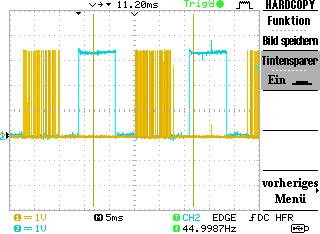
This is the correct behaviour, and it only appears that way when I use the epwm for the low side.
When I use normal GPIO, this happens:
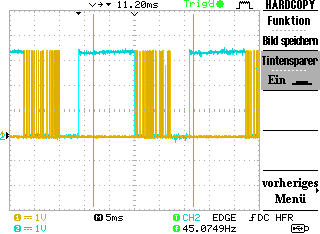
And it only happens on one phase, I cannot predict (it just switched to V). It does not even matter, what IO I am using. What am I doing wrong?
Apart from that I was informed, my motor is using too much current (three times as much as when it was tested with a competitor's chip I don't know). I am using the epwms for the low side to avoid shoot-through - afaic I cannot explain the high current consumption.
Apart from that, there is still another issue. One if-condition is ignored, I will show you the screenshot:

I also tried to Combine the conditions with "&&", there was no change.
I am looking Forward to your help!
Regards,
E
PS: i was experiencing some Trouble while editing, it may look weird, but sometimes while I was writing, the writing direction changed and I was not able to put the cursor where needed.
