This thread has been locked.

If you have a related question, please click the "Ask a related question" button in the top right corner. The newly created question will be automatically linked to this question.

F28069 scalar (V/F) control of ACIM motor phase current distortion issue

Other Parts Discussed in Thread: TMS320F28069

Hi Chris,

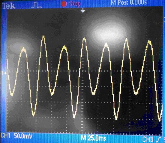
I have designed a VFD with F28069 for a customer and it works great, however, I found a motor phase current distortion issue when it works at scalar (V/F) control mode. The current distortion happens while the motor is running at frequency between 29Hz and 39Hz. The VFD settings are fc = 8kHz, PWM deadband = 2us. I also tried another brand VFD at the same test conditions, and it does not have such issue.

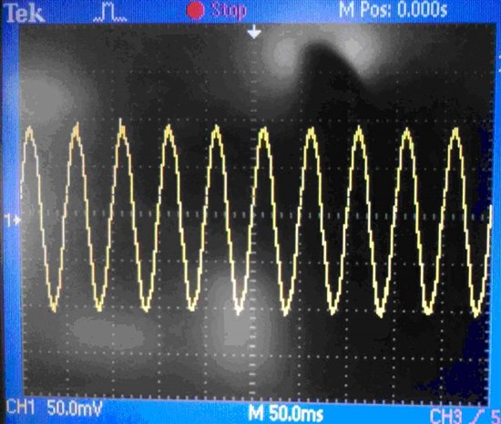
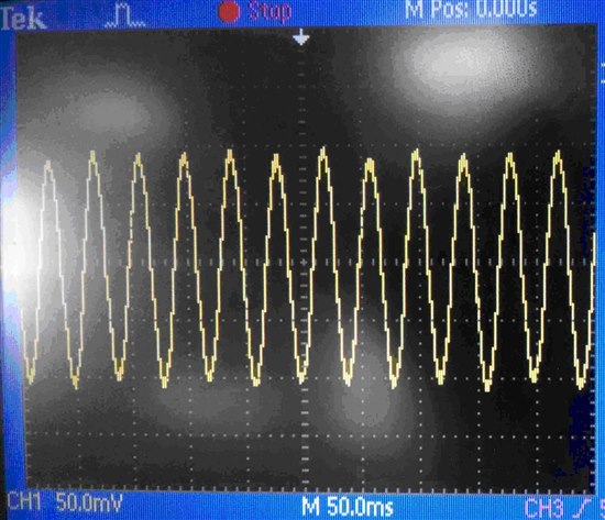
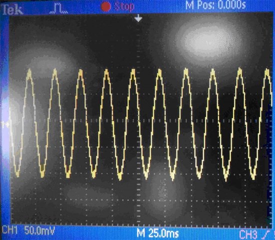
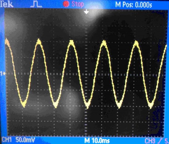
Please see below photos of motor phase currents at different running frequencies.

Fig. 1  Motor U Phase Current at 20Hz

Fig. 2  Motor U Phase Current at 25Hz

Fig. 3   Motor U Phase Current at 30Hz

Fig. 4  Motor U Phase Current at 35Hz

Fig. 5  Motor U Phase Current at 40Hz

Fig. 6  Motor U Phase Current at 50Hz

My VFD scalar control code is from HVMotorCtrl+PfcKit_v2.0 HVACI_Scalar project. I think it might have some issues. Could you please help me on this issue?

Thanks a lot.

Biao

  • This is not distortion but control instability.

    You need tuning of closed loop control parameters, PI or whatever.

  • Hi Joy,

    Open loop is used in my project. Anyway, Thanks.

    Biao

  • Hi Biao,

    Sensored or sensorless closed loop control is the cure for this kind of behaviour. Seems like mechanical instability caused by slot harmonics (combined with dead time effects).

    Regards

    Ibrahim

  • Hi Ibrahim,

    Thanks for you reply. I agree to your analysis on the issue.

    A sensorless V/F mode is used in my product. According to Ti's F2803x/6x scalar (V/F) reference code, I could not find any clue for a sensorless V/F with closed loop control. Could you please let me know how to do it?

    The following is Ti's F2803x/6x scalar (V/F) reference code. I think there is only sensored closed loop can be selected.

    // ------------------------------------------------------------------------------
    //  Connect inputs of the RMP module and call the ramp control macro
    // ------------------------------------------------------------------------------
        rc1.TargetValue = SpeedRef;        
        RC_MACRO(rc1)
        
    // ------------------------------------------------------------------------------
    //    Connect inputs of the PI modules and compute the PI speed
    //    controller.
    // ------------------------------------------------------------------------------  
        if (SpeedLoopCount == SpeedLoopPrescaler)
        {
          pi_spd.Ref = rc1.SetpointValue;
          pi_spd.Fbk = speed1.Speed;
          PI_MACRO(pi_spd);
          SpeedLoopCount = 1;
        }
        else SpeedLoopCount ++;
        
    // ------------------------------------------------------------------------------
    //    Connect inputs of the VOLT_PROF module for open-loop or closed-loop
    // ------------------------------------------------------------------------------
        if (ClosedLoopFlag==FALSE)
         {    
              vhz1.Freq = rc1.SetpointValue;                    // Open-loop V/f control
              pi_spd.ui=0;
              pi_spd.i1=0;
          }
         else
              vhz1.Freq = rc1.SetpointValue + pi_spd.Out;    // Speed closed-loop V/f control

    // ------------------------------------------------------------------------------
    //    Call the volt profile macro
    // ------------------------------------------------------------------------------
           VHZ_PROF_MACRO(vhz1);

    // ------------------------------------------------------------------------------
    //    Connect inputs of the SVGEN_MF module and call the space-vector gen. macro
    // ------------------------------------------------------------------------------
        svgen_mf1.Gain = vhz1.VoltOut;     
        svgen_mf1.Freq = vhz1.Freq;  
        SVGENMF_MACRO(svgen_mf1);

    // ------------------------------------------------------------------------------
    //  Call the QEP macro (if incremental encoder used for speed sensing)
    //  Connect inputs of the SPEED_FR module and call the speed calculation macro
    // ------------------------------------------------------------------------------
        QEP_MACRO(1,qep1)

        speed1.ElecTheta = _IQ24toIQ((int32)qep1.ElecTheta);
        speed1.DirectionQep = (int32)(qep1.DirectionQep);
        SPEED_FR_MACRO(speed1)

    // ------------------------------------------------------------------------------
    //  Call the CAP macro (if sprocket or spur gear used for speed sensing)
    //  Connect inputs of the SPEED_PR module and call the speed calculation macro
    // ------------------------------------------------------------------------------
        CAP_MACRO(1,cap1)

        if(cap1.CapReturn ==0)                                 // Check the capture return
        {
            speed2.EventPeriod=(int32)(cap1.EventPeriod);    // Read out new event period
            SPEED_PR_MACRO(speed2)                              // Call the speed macro      
        }

    // ------------------------------------------------------------------------------
    //    Connect inputs of the PWM_DRV module and call the PWM signal generation
    //    update function.
    // ------------------------------------------------------------------------------
        pwm1.MfuncC1 = svgen_mf1.Ta;  
        pwm1.MfuncC2 = svgen_mf1.Tb;   
        pwm1.MfuncC3 = svgen_mf1.Tc;
        PWM_MACRO(1,2,3,pwm1)                            // Calculate the new PWM compare values   

    Thank you for your help.

    Biao

  • Hi Biao,
    This is bala from india.Shall i know the Tms320f28069 IC is support to v/f scalar control method?
  • Hi Biao,
    Thanks for your reply...Shall i know what is the switching frequency range and In which algorithm you are using ?