This thread has been locked.

If you have a related question, please click the "Ask a related question" button in the top right corner. The newly created question will be automatically linked to this question.

Enabling or Setting the GPIO12 and GPIO16 pin to 1 in ePWM module

Other Parts Discussed in Thread: TMS320F28335

Dear friends,

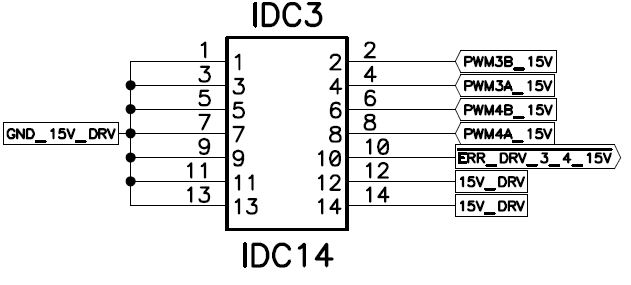
I am using 1-A, 1-B, 3-A and 3-B as the ePWM ouputs. So I am using both the 14-pin ePWM outputs in the hardware, which are connected to each of its MOSFET driver IC (whose picture I have uploaded).

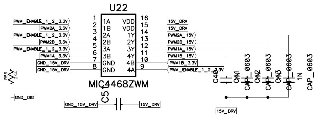
I can see U22-MIC4468ZWM, a MOSFET driver IC before the 14-pin PWM output in the DSP TMS320F28335. I am working on a simple ePWM module in the DSP. My aim is to get 4 PWM pulses from the 14-pin PWM output in the hardware.

 I am getting the desired output as I have programmed, according to my requirements in the pins--> PWM1A_3.3V, PWM1B_3.3V of MOSFET IC driver 1 and PWM3A_3.3V, PWM3B_3.3V of MOSFET IC driver 2 respectively . But not in the pin PWM1A_15V, PWM1B_15V, PWM3A_15V and PWM3B_15V.

So in order to get the ouputs in the 15V pin of the MOSFET driver IC, I have to enable the PWM_ENABLE_1_2_3.3V pin in the DSP itself whose pin configuration are as follows:

  PWM_Enable_1_2_3.3V ---> 21 (Pin number) ---> GPIO12

  PWM_Enable_3_4_3.3V ---> 27 (Pin number) ---> GPIO16

Finally my aim is to enable or set GPIO12 and GPIO16 pins to 1, for which I have included the following codes in the main()

GpioCtrlRegs.GPADIR.bit.GPIO12 = 1;
GpioCtrlRegs.GPADIR.bit.GPIO16 = 1;
EDIS;
GpioDataRegs.GPASET.bit.GPIO12 = 1;
GpioDataRegs.GPASET.bit.GPIO16 = 1;
InitEPwm1();  // is for the PWM1
InitEPwm3();  // is for the PWM3
EALLOW;

Note: 1 Also as I have been advised to not to enable the pullup on GPIO12 and GPIO16, I just commented the below lines in DSP2833x_EPwm.c file so that it become ineffective:-

// GpioCtrlRegs.GPAPUD.bit.GPIO12 = 0; // Enable pull-up on GPIO12 (TZ5)
// GpioCtrlRegs.GPAPUD.bit.GPIO16 = 0; // Enable pull-up on GPIO16 (TZ5)

After doing all these, I am still unable to set the GPIO12 and GPIO16 to 1 and thats my problem is concerned with

Question 1: What should I do the configuration of TZ (Trip zone) in these pins i.e. GPIO12 and GPIO16. Is it necessary to configure it as TZ1 and TZ5 in the DSP2833x_EPwm.c file as shown below  ???? or not to configure so that I can comment this line in DSP2833x_EPwm.c

GpioCtrlRegs.GPAMUX1.bit.GPIO12 = 1; // Configure GPIO12 as TZ1
GpioCtrlRegs.GPAMUX1.bit.GPIO16 = 3; // Configure GPIO13 as TZ5

Question 2: Is there any mistake in the codes I am using to enable GPIO12 and GPIO16 ?? Or is there anything I have to concern about when enabling these to pins in the DSP ?? Or any other changes I have to make in DSP2833x_EPwm.c file in order to set the GPIO12 and GPIO16 pins to 1.

(Attached pictures are 1) 14-pin output for PWM_1_2,

                                    2) 14-pin output for PWM_3_4,

                                    3) MOSFET driver IC for PWM_1_2 and

                                    4) MOSFET driver IC for PWM_3_4

)


Thanks in advance !

  • Hello,

    Seems that your purpose is to make GPIO12 and 16 as GP outputs.

    In this case you need to set:

    GPADIR into 1 (output)

    GPAMUX into 0 (gpio)

    and if you want to disable the pullup, GPAPUD is set into 1 (0, means enabled, is the default).

    And don't forget to put EALLOW and EDIS before and after the setting.

    Hope this helps.

    Best regards,

    Maria

  • Thanks Maria !

    1) As you have told I am making the below changes in the main itself


    EALLOW;

    GpioCtrlRegs.GPADIR.bit.GPIO12 = 1;
    GpioCtrlRegs.GPADIR.bit.GPIO16 = 1;

    GpioCtrlRegs.GPAMUX1.bit.GPIO12 = 0;

    GpioCtrlRegs.GPAMUX1.bit.GPIO16 = 0;

    GpioCtrlRegs.GPAPUD.bit.GPIO12 = 1;

    GpioCtrlRegs.GPAPUD.bit.GPIO16 = 1;
    EDIS;
    GpioDataRegs.GPASET.bit.GPIO12 = 1;
    GpioDataRegs.GPASET.bit.GPIO16 = 1;
    EALLOW;

    Is it ok ?

    2) Should I do these in main itself or in DSP2833x_EPwm.c file as I am using two functions named 

    InitEPwm1Gpio();
    InitEPwm3Gpio();

    whose coding/settings are in DSP2833x_EPwm.c. In this file itself I can find the codes of other pins also for example i can find whether pin GPIO12 is pullup enabled or TZ enabled, and so on.

    So, where should I make the changes in main() or in DSP2833x_EPwm.c ?

  • Hello,

    1. The settings of GPIO12 and 16 are ok except GpioCtrlRegs.GPAMUX1.bit.GPIO16 = 0;

    I think it should be GpioCtrlRegs.GPAMUX2.bit.GPIO16 = 0;

    Please check the datasheet to make sure.

    2. I don't know what inside your DSP2833x_EPwm.c.

    You can put the settings (GPADIR, GPAMUX,GPAPUD) anywhere before the main loop (but after the init base address if used) and make sure these settings are not overlapped by existing settings (that maybe exist before, maybe in InitEPwm1Gpio() and InitEPwm3Gpio()).

    And actually you can put these settings in InitEPwm1Gpio() or InitEPwm3Gpio() and call the function before main loop.

    About GPASET, you can put it anywhere after this setting based on your purpose.

    Best regards,

    Maria

  • Dear Miss.Maria,

     Thanks for your esteemed replies and guidance....

    I have small doubts....

    1) Should I enable the asynchronous input (no qualification) for GPIO12 and GPIO16 by using the below code ?

    GpioCtrlRegs.GPAQSEL1.bit.GPIO12 = 3;

    GpioCtrlRegs.GPAQSEL2.bit.GPIO16 = 3;

    If I have to disable it, should i simply remove the line or have to edit something in the above two lines ?

    2) What is the difference between the three below lines ?

    GpioCtrlRegs.GPAMUX2.bit.GPIO16 = 0;

    and 

    GpioCtrlRegs.GPAMUX2.bit.GPIO16 = 1;

    and

    GpioCtrlRegs.GPAMUX2.bit.GPIO16 = 3;

    Which one should be used in my case ?

    Thanks in advance !

  • Dear Miss.Marisa,

      Thanks a lot for your prompt explanation.

      Now its working. As I am a beginner, I am learning slowly.

      Thanks once again !

  • Hello,

    That's great to hear that your code is working.

    About your doubts:

    1.

    Charanraj Mohan said:

    GpioCtrlRegs.GPAQSEL1.bit.GPIO12 = 3;

    GpioCtrlRegs.GPAQSEL2.bit.GPIO16 = 3;

    You don't need this as your GPIO is output. This is used if your GPIO is input. Just disable/comment out the lines.

    2.

    Charanraj Mohan said:

    GpioCtrlRegs.GPAMUX2.bit.GPIO16 = 0;

    and 

    GpioCtrlRegs.GPAMUX2.bit.GPIO16 = 1;

    and

    GpioCtrlRegs.GPAMUX2.bit.GPIO16 = 3;

    You need to use GpioCtrlRegs.GPAMUX2.bit.GPIO16 = 0; because in your case you need GP input/output (0).

    This GPAMUX is used to select which function you need since the pin can be used other than input/output.

    For GPIO16, it can be used as SPI (1), CAN (2), and TZ (3) besides GPIO. Please check the datasheet to know it correctly.

    Because your code is working now, please verify this thread to mention it as closed thread.

    And if you have other question, don't be hesitated to create new thread.

    Good luck!

    Best regards,

    Maria

  • Thanks Miss.Maria !

    Your explanation were really useful !