This thread has been locked.

If you have a related question, please click the "Ask a related question" button in the top right corner. The newly created question will be automatically linked to this question.

CLA - Start wrong Task after hardware reset

Other Parts Discussed in Thread: TMS320F28035

Hi, I've got a problem with the behavior of the CLA. I hope you can help me.

My developer environment

Microcontroller:  TMS320F28035

Programmer:      Texas Instruments XDS100v2 USB Emulator

CCS Version:      5.2.1.00018

Compiler:            TI C2000 v6.2.4

The sequence of the software is really simple and looks like this:

// Initialization of the peripheral
while(1)
{
Cla1ForceTask8AndWait();
}

My problem

When I start the Software in the debug mode, the CLA reaches the Task 8 and stops at the set breakpoint. The behavior is the same after a CPU Reset in the CCS Debug-Window (Ctrl+Shift+R). But when I'm in the debug mode and do a hardware reset over the !XRS Pin, the CLA starts just the Task 1 over and over. The Task 8 is never reached.
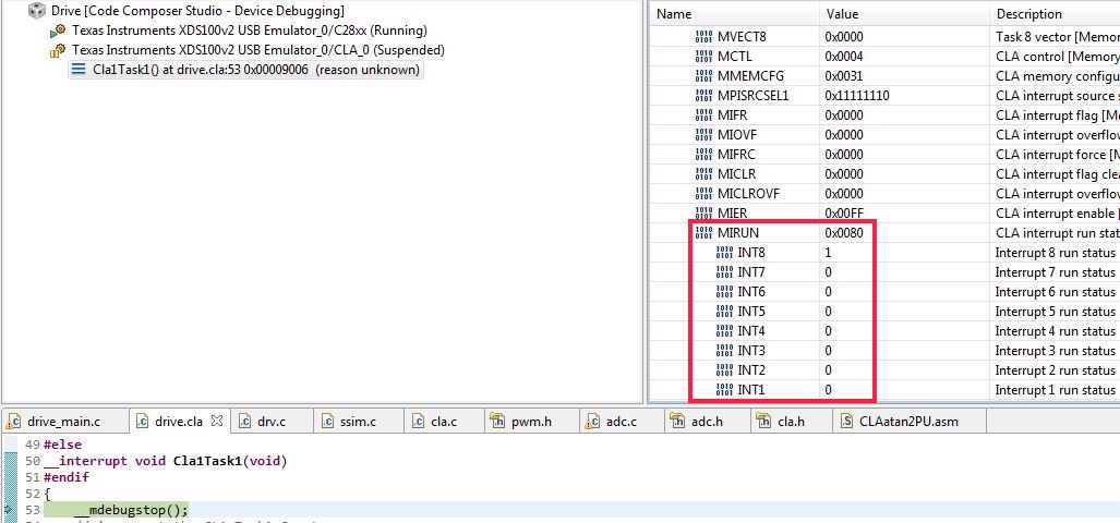
In the picture above you can see, that the CLA stopped at the breakpoint in the Task 1. The register list shows, that the INT8 bit of the MIRUN is set in the INT1 Bit is cleared. Would mean, the CLA Task 8 is executing and the CLA Task 1 is not executing. Is there an explanation for the behavior?

Thanks for your help.

  • Hi Sven,

    After you assert the XRSn pin, whats the value of the MVECT1 and MVECT8 registers?? It looks to me like Task 8 is being triggered, but its MVECT8 shows 0x0000 as the offset, which means it would be executing from 0x9000 which i assume is where Cla1Task1 is located at.

  • Hi Vishal,


    Thanks for your answer. That was the right approach. I had to change the initialization sequence of the PIE Vector Table. But I don’t understand the reason why it works now.


    My previous sequence:

    // Copy the CLA Code to RAM
    // Initialize the PIE Vector Table
    // Set up Oscillator
    // Set up PLL
    // Set the PIE Vector Table to a default state
    // Set up peripheral clocks
    // Set up CLA
    // Set up peripheral
    // main loop


    My new sequence:

    // Copy the CLA Code to RAM
    // Set up Oscillator
    // Set up PLL
    // Set up PIE Vector Table to a default state
    // Set up Peripheral Clocks
    // Initialize the PIE Vector Table
    // Set up CLA
    // Set up peripheral
    // main loop


    I have two assumptions:

    1. “Set the PIE Vector Table to a default state” should not be called after “Initialize the PIE Vector Table”. Perhaps the PIE Vector Table Setting would be overwritten?

    2. All clocks have to run before initializing the PIE Vector Tables.


    So what do you think Vishal? Is there an application note with a hint?

  • Hi Sven,

    Sven Flachm��ller said:
    “Set the PIE Vector Table to a default state” should not be called after “Initialize the PIE Vector Table”. Perhaps the PIE Vector Table Setting would be overwritten?

    The MVECTx registers belong to the CLA module, they arent related to the PIE registers. When you assert the XRSn pin it resets these registers to zero so you have to reinitialize them after every reset. Its possible that you were writing to the MVECT regs before running InitSysCtrl() -  the clock to the CLA would not be enabled before InitSysCtrl(), but then you shouldn't be able to write to any of the CLA registers so im not quite sure how changing the order is affecting the code.