This thread has been locked.

If you have a related question, please click the "Ask a related question" button in the top right corner. The newly created question will be automatically linked to this question.

TMDSHVTRINSPIN HV kit

Other Parts Discussed in Thread: CONTROLSUITE, TMDSHVMTRINSPIN

TMDSHVMTRINSPIN 'SC_ERR_FTDI_OPEN'  error connection failure.

Dear Sir;

I have received a new TMDSHVTRINSPIN HV kit.  I also have the following hardware:

TI Experimenter's Kit - Docking-Stn USB-EMU [R3]

TI  Peripheral Explorer

Several Control cards:

F2802xx controlCARD (Piccolo-A) Release 1.0 with a F28027PTT chip

F28335 controlCARD Release 2.2 with a F28335ZJZA

F28069 controlCARD Release 1.1 with a F28069UPZPS

F2806x ISO controlCARD Release 0.4 with a F28069MPZT chip  

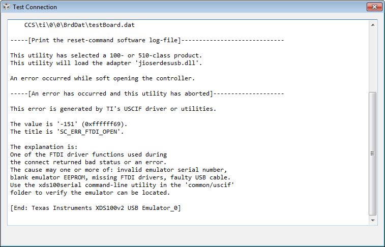
My challenge seems to be the USB interface on the TMDSHVMTRINSPIN kit.  I have successfully used the F28027, F28335 and the F28069 and F28069MISO controlCARDS in the Experimenter's kit and the Code Composer Studio, Version: 6.0.0.00190 communicates through the USB interface and I have successfully changed flashing speed on the "flashing light" program on all of these cards.  However, the USB interface does not appear to be working on the TMDSHVMTRINSPIN and issues the TMDSHVMTRINSPIN 'SC_ERR_FTDI_OPEN'  error connection failure.  If I connect a scope to the any of the pins of the functioning Experimenter's kit, JTAG  J2 Pins 1,3,7,9 (DIL-14) and run the XDS100v1 (or v2) "Test Connection".  I get data signals.  This is with the USB connected and SW1 powered by USB.  However, if I run the same test on the TMDSHVMTRINSPIN,  with the USB plugged in (M3 LD1 is on indicating 3V3_ISO is functioning).  M6 is receiving external power (M6 LD1 is ON).  The controlCARD (typically F28027 LD1 is also ON. Placing a scope on signals TMS-ISO, TDI-ISO, TDO-ISO, and TCK-ISO via M3-J2 jumper block (Pins 1,3, 7, 9) indicates no data signals at all referenced to the ISO ground.   The following message is issued: 

The value is '-151' (0xffffff69).
The title is 'SC_ERR_FTDI_OPEN'.

I have also gone through the combinations of J9(TRSTn) and M3-J5 with no luck.  USB Data-P and Data-M have signals.  Can you help?


  • Hello,

    For the ControlCard without ISO, what is your setting for [Main]-J9 and [M3]-J5?

    [Main]-J9 should be populated and [M3]-J5 should be unpopulated if the ControlCard is non-ISO.

    For ControlCard with ISO, the setting is opposite.

    Best regards,

    Maria

  • Agreed.

    For:

    F2802xx controlCARD (Piccolo-A) Release 1.0 with a F28027PTT chip

    [Main]-J9 populated

    [M3]-J5 unpopulated

    --------------------------------------------------------------------------

    F28335 controlCARD Release 2.2 with a F28335ZJZA

    Main]-J9 populated

    [M3]-J5 unpopulated

    --------------------------------------------------------------------------

    F28069 controlCARD Release 1.1 with a F28069UPZPS

    Main]-J9 populated

    [M3]-J5 unpopulated

    --------------------------------------------------------------------------

    F2806x ISO controlCARD Release 0.4 with a F28069MPZT chip  

    Main]-J9 unpopulated

    [M3]-J5 populated

    ---------------------------------------------------------------------------

    I have been working mainly with F28027 and F28335, all of these jumper combinations have been tried and the emulator does not appear to be responding.  As reflected in the schematic sheet located in

    C:\ti\controlSUITE\development_kits\HVMotorCtrl+PfcKit_v2.1\~HVMotorCtrl+PFC-HWdevPkg\HVMotorCtrl+PFCKit-R1.1

    on page 6 of the sheet entitled "ISO-USB-to-JTAGII (macro)" on the lower left side shows connecting J5 will pull pin 4 (RST-in) down on the FT2232D chip. and sheet 1 entitled "H. Voltage DMC+PFC [R1.1]" dated 11/17/2011, allows TRSTn to be connected to pin 99 on the main J1 controlCARD interface. These can be cross referenced with sheets

    C:\ti\controlSUITE\development_kits\~controlCARDs\CC2833xHWdevPkg\F28335controlCARD HWDevPkg ZJZ [R2.2]

    and sheet

    C:\ti\controlSUITE\development_kits\~controlCARDs\CC2802xHWdevPkg

    Since the emulator on the TMDSHVTRINSPIN did not work,  but the emulator on the Experimenter's kit and on the Peripheral Explorer were functioning correctly (via the use of the command line test software found in directory as per the CCSv6 test function):

    C:\ti\ccsv6\ccs_base\common\uscif\dbgjtag 

    and using the command line argc, argv flags

    C:\ti\ccsv6\ccs_base\common\uscif>dbgjtag -f C:\Users\kloesel\AppData\Local\TEXASI~1\CCS\ti\0\0\BrdDat\testBoard.dat -rv -o -F inform,logfile=yes -S pathlength -S integrity

    I then reviewed sheet :

    C:\ti\controlSUITE\development_kits\~ExperimentersKits\ExperimentersKit-HWdevPkg\USBDockingStation_Schematic [R3].pdf

    (all schematics were compared with hardware and versions verified and PCB layouts verified)

    the review indicates that all the resistors and capacitors surrounding the FTDI2232D chip were the same on two boards (Experimenter's kit and TMDSHVMTRINSPIN kit).  The power pins on the FDTI2232D were checked an demonstrated proper voltages of 3.3V_ISO and 5V_USB.  The crystal oscillator was checked and was approximately running at 6mHz.  On the TMDSHVMTRINSPIN, the power voltages were verified on the other side of the TI ISO7220.  

    All of this work was performed and the emulator is still not communicating.  Can you help?

    Thanks.

  • Hello,

    Kurt Kloesel said:
    The value is '-151' (0xffffff69).
    The title is 'SC_ERR_FTDI_OPEN'.

    Just want to confirm, is this error appeared in CCS?

    Also, did you find XDS100 recognized in Device Manager?

    Did you use the same USB cable for Experimenter Kit and for TMDSHVMTRINSPIN?

  • Please check also this thread and let us know whether this helps to solve the FTDI problem or not.

    http://e2e.ti.com/support/development_tools/code_composer_studio/f/81/t/248800.aspx

    Best regards,

    Maria

  • Both cables give same error on TMDSHVMTRINSPIN.  Both cables are successful on Experimenter's Board.

    The test error from CCSv6 is:


    The test was also performed through DOS-command line:

    And yields the same result on both cables.  Both cables were successful on the Experimenter's Board, the CCSv6 GUI yields the same results as the command.com:

    The bitmaps are a little fuzzy, but you get the idea. The FTDI driver was also upgraded to the latest version:

    The TMDSHVMTRINSPIN interface is still not functioning.

    Thanks

  • Maria -

    Well, it looks like the FT2232D had a blank EEPROM (all FF's).  I have programmed it, using both MProg and FT_prog as the other blogs suggested.  It's a slight improvement.  It seems to be at least recognizing the chip, but it is issuing JTAG integrity errors.  Your co-worker Ki-Soo Lee,  seems to know something about this.  Apparently there are different file formats for MProg (*.ept) and FT_prog (*.xml).  Do you have any experience programming the FT2232D on the TMDSHVTRINSPIN?  I do not want to follow the route suggested by the customer at the end of his blog, because the Experimenter Boards are working just fine.

    Thanks, Kurt

  • Maria -

    and possibly Ki-Soo Lee,

    OK.  It's all working.  I forgot to power up the F28335 controlCARD on the other side of the ISO7220 chips (doh!).  I ended up sucking the brains out of one of the Experimenter Board FT2232D EEPROM's and installing it into the TMDSHVMTRINSPIN FT2232D chip, but I'm pretty sure the other *.ept file would have worked.  Thanks for the tips.  That was quite a trouble shooting adventure.  Now - let's spin some motors with this baby.  I'm pretty sure one could use MProg and FT_prog together to convert between *.ept and *.xml formats.

    Kurt 

  • Great!

    Hope you have nice time with your spinning motor!

    PS: Can you close the thread?

    Best regards,

    Maria