This thread has been locked.

If you have a related question, please click the "Ask a related question" button in the top right corner. The newly created question will be automatically linked to this question.

adc_isr not serviced on LaunchPadXL

Other Parts Discussed in Thread: CONTROLSUITE

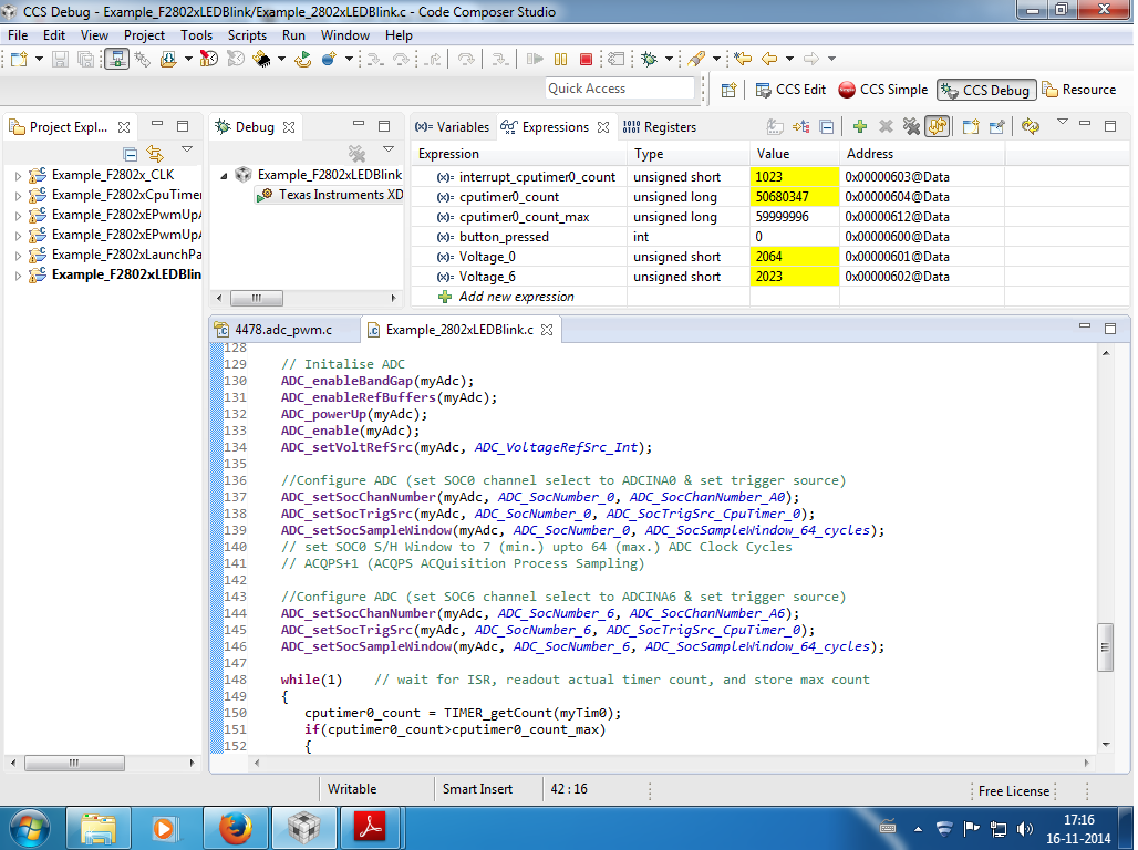
I'm using a C2000 LaunchPadXL withF28027 and the following code, which light up the leds 1&3 or 2&4 (GPIO 0/1/2/3), depending on the state of the onboard button (GPIO12). It also shows the CLK/4 at GPIO 18. This works fine, however why is the ISR not serviced in this case? What do I wrong?

//#############################################################################
// COMMENTS CLK/ADC/GPIO example
// example program with debug expressions
// button_pressed, loop_counter, isr_counter, Voltage_6
//#############################################################################

#include "DSP28x_Project.h"     // Device Headerfile and Examples Include File

#include "f2802x_common/include/clk.h"
#include "f2802x_common/include/gpio.h"
#include "f2802x_common/include/pll.h"
#include "f2802x_common/include/wdog.h"
#include "f2802x_common/include/adc.h"
#include "f2802x_common/include/pie.h"

int button_pressed = 0;
long int loop_counter = 0;
long int isr_counter = 0;

uint_least16_t Voltage_6;

CLK_Handle myClk;
GPIO_Handle myGpio;
WDOG_Handle myWDog;
PLL_Handle myPll;
ADC_Handle myADC;

void main(void)
{
    // Initialize all the handles needed for this application    
    myClk = CLK_init((void *)CLK_BASE_ADDR, sizeof(CLK_Obj));
    myGpio = GPIO_init((void *)GPIO_BASE_ADDR, sizeof(GPIO_Obj));
    myPll = PLL_init((void *)PLL_BASE_ADDR, sizeof(PLL_Obj));
    myWDog = WDOG_init((void *)WDOG_BASE_ADDR, sizeof(WDOG_Obj));
    myADC = ADC_init((void *)ADC_BASE_ADDR, sizeof(ADC_Obj));

    // Perform basic system initialization    
    WDOG_disable(myWDog);

    //Select the internal oscillator 1 as the clock source
    CLK_setOscSrc(myClk, CLK_OscSrc_Internal);
    CLK_enableAdcClock(myClk);
    // Setup the PLL for x10 /2 which will yield 10MHz * 12 / 2 = 60MHz
    PLL_setup(myPll, PLL_Multiplier_12, PLL_DivideSelect_ClkIn_by_2);
    
    // Initalize GPIO
    GPIO_setDirection(myGpio, GPIO_Number_18, GPIO_Direction_Output);
    GPIO_setMode(myGpio, GPIO_Number_18, GPIO_18_Mode_XCLKOUT);  // SYSCLKOUT/4 op GPIO-18
    
    GPIO_setPullUp(myGpio, GPIO_Number_12, GPIO_PullUp_Disable);
    GPIO_setMode(myGpio, GPIO_Number_12, GPIO_12_Mode_GeneralPurpose);  // onboard push button
    GPIO_setDirection(myGpio, GPIO_Number_12, GPIO_Direction_Input);

    GPIO_setPullUp(myGpio, GPIO_Number_0, GPIO_PullUp_Enable);			// pull-up 20k on board led 1
    GPIO_setMode(myGpio, GPIO_Number_0, GPIO_0_Mode_GeneralPurpose);
    GPIO_setDirection(myGpio, GPIO_Number_0, GPIO_Direction_Output);

    GPIO_setPullUp(myGpio, GPIO_Number_1, GPIO_PullUp_Enable);
    GPIO_setMode(myGpio, GPIO_Number_1, GPIO_0_Mode_GeneralPurpose);
    GPIO_setDirection(myGpio, GPIO_Number_1, GPIO_Direction_Output);

    GPIO_setPullUp(myGpio, GPIO_Number_2, GPIO_PullUp_Enable);
    GPIO_setMode(myGpio, GPIO_Number_2, GPIO_0_Mode_GeneralPurpose);
    GPIO_setDirection(myGpio, GPIO_Number_2, GPIO_Direction_Output);

    GPIO_setPullUp(myGpio, GPIO_Number_3, GPIO_PullUp_Enable);
    GPIO_setMode(myGpio, GPIO_Number_3, GPIO_0_Mode_GeneralPurpose);
    GPIO_setDirection(myGpio, GPIO_Number_3, GPIO_Direction_Output);

    // Initalize ADC
    ADC_enableBandGap(myADC);
    ADC_enableRefBuffers(myADC);
    ADC_powerUp(myADC);
    ADC_enable(myADC);
    ADC_setVoltRefSrc(myADC, ADC_VoltageRefSrc_Int);
    ADC_enableInt(myADC, ADC_IntNumber_6);
    ADC_setIntMode(myADC, ADC_IntNumber_6, ADC_IntMode_ClearFlag);   // EOC (End Of Conversion) or ClearFlag

  while(1)		// loop and wait for interrupt
  {
	if(GPIO_getData(myGpio, GPIO_Number_12) != 1) // board button GPIO_12 not pressed
    {
    	GPIO_setHigh(myGpio, GPIO_Number_0); // led off (not pressed)
    	GPIO_setLow(myGpio, GPIO_Number_1);
    	GPIO_setHigh(myGpio, GPIO_Number_2);
    	GPIO_setLow(myGpio, GPIO_Number_3);
    	button_pressed = 0;
    }
    else
    {
    	GPIO_setLow(myGpio, GPIO_Number_0); // led on (pressed)
    	GPIO_setHigh(myGpio, GPIO_Number_1);
    	GPIO_setLow(myGpio, GPIO_Number_2);
    	GPIO_setHigh(myGpio, GPIO_Number_3);
    	button_pressed = 1;
    }
	loop_counter++;
  }
}

interrupt void adc_isr(void)
{
	isr_counter++;
	Voltage_6 = ADC_readResult(myADC, ADC_ResultNumber_6);
	ADC_clearIntFlag(myADC, ADC_IntNumber_6); // Clear ADCINT6 flag reinitialize for next SOC (start of conversion)
	return;
}


//===========================================================================
// No more.
//===========================================================================

  • Hi Bart,

    I checked your code, you've not at all enbled the ADC interrupt in your code. ie configure the PIE register.

    Please refer this code and configure accordingly:

    //#############################################################################
    //
    //  File:   f2802x_examples/adc_soc/Example_F2802xAdcSoc.c
    //
    //  Title:  F2802x ADC Start-Of-Conversion (SOC) Example Program.
    //
    //  Group:          C2000
    //  Target Device:  TMS320F2802x
    //
    //! \addtogroup example_list
    //!  <h1>ADC Start-Of-Conversion (SOC)</h1>
    //!
    //!   Interrupts are enabled and the ePWM1 is setup to generate a periodic
    //!   ADC SOC - ADCINT1. Two channels are converted, ADCINA4 and ADCINA2.
    //!
    //!   Watch Variables:
    //!
    //!   - Voltage1[10] - Last 10 ADCRESULT0 values
    //!   - Voltage2[10] - Last 10 ADCRESULT1 values
    //!   - ConversionCount - Current result number 0-9
    //!   - LoopCount - Idle loop counter
    //
    //  (C) Copyright 2012, Texas Instruments, Inc.
    //#############################################################################
    // $TI Release: PACKAGE NAME $
    // $Release Date: PACKAGE RELEASE DATE $
    //#############################################################################
    
    #include "DSP28x_Project.h"     // Device Headerfile and Examples Include File
    
    #include "f2802x_common/include/adc.h"
    #include "f2802x_common/include/clk.h"
    #include "f2802x_common/include/flash.h"
    #include "f2802x_common/include/gpio.h"
    #include "f2802x_common/include/pie.h"
    #include "f2802x_common/include/pll.h"
    #include "f2802x_common/include/pwm.h"
    #include "f2802x_common/include/wdog.h"
    
    // Prototype statements for functions found within this file.
    __interrupt void adc_isr(void);
    void Adc_Config(void);
    
    // Global variables used in this example:
    uint16_t LoopCount;
    uint16_t ConversionCount;
    uint16_t Voltage1[10];
    uint16_t Voltage2[10];
    
    ADC_Handle myAdc;
    CLK_Handle myClk;
    FLASH_Handle myFlash;
    GPIO_Handle myGpio;
    PIE_Handle myPie;
    PWM_Handle myPwm;
    
    void main(void)
    {
        
        CPU_Handle myCpu;
        PLL_Handle myPll;
        WDOG_Handle myWDog;
        
        // Initialize all the handles needed for this application    
        myAdc = ADC_init((void *)ADC_BASE_ADDR, sizeof(ADC_Obj));
        myClk = CLK_init((void *)CLK_BASE_ADDR, sizeof(CLK_Obj));
        myCpu = CPU_init((void *)NULL, sizeof(CPU_Obj));
        myFlash = FLASH_init((void *)FLASH_BASE_ADDR, sizeof(FLASH_Obj));
        myGpio = GPIO_init((void *)GPIO_BASE_ADDR, sizeof(GPIO_Obj));
        myPie = PIE_init((void *)PIE_BASE_ADDR, sizeof(PIE_Obj));
        myPll = PLL_init((void *)PLL_BASE_ADDR, sizeof(PLL_Obj));
        myPwm = PWM_init((void *)PWM_ePWM1_BASE_ADDR, sizeof(PWM_Obj));
        myWDog = WDOG_init((void *)WDOG_BASE_ADDR, sizeof(WDOG_Obj));
    
        // Perform basic system initialization    
        WDOG_disable(myWDog);
        CLK_enableAdcClock(myClk);
        (*Device_cal)();
        
        //Select the internal oscillator 1 as the clock source
        CLK_setOscSrc(myClk, CLK_OscSrc_Internal);
        
        // Setup the PLL for x10 /2 which will yield 50Mhz = 10Mhz * 10 / 2
        PLL_setup(myPll, PLL_Multiplier_10, PLL_DivideSelect_ClkIn_by_2);
        
        // Disable the PIE and all interrupts
        PIE_disable(myPie);
        PIE_disableAllInts(myPie);
        CPU_disableGlobalInts(myCpu);
        CPU_clearIntFlags(myCpu);
        
    // If running from flash copy RAM only functions to RAM   
    #ifdef _FLASH
        memcpy(&RamfuncsRunStart, &RamfuncsLoadStart, (size_t)&RamfuncsLoadSize);
    #endif   
    
        // Setup a debug vector table and enable the PIE
        PIE_setDebugIntVectorTable(myPie);
        PIE_enable(myPie);
    
        // Register interrupt handlers in the PIE vector table
        PIE_registerPieIntHandler(myPie, PIE_GroupNumber_10, PIE_SubGroupNumber_1, (intVec_t)&adc_isr);
    
        // Initialize the ADC
        ADC_enableBandGap(myAdc);
        ADC_enableRefBuffers(myAdc);
        ADC_powerUp(myAdc);
        ADC_enable(myAdc);
        ADC_setVoltRefSrc(myAdc, ADC_VoltageRefSrc_Int);
    
        // Enable ADCINT1 in PIE
        PIE_enableAdcInt(myPie, ADC_IntNumber_1);
        // Enable CPU Interrupt 1
        CPU_enableInt(myCpu, CPU_IntNumber_10);
        // Enable Global interrupt INTM
        CPU_enableGlobalInts(myCpu);
        // Enable Global realtime interrupt DBGM
        CPU_enableDebugInt(myCpu);
    
        LoopCount = 0;
        ConversionCount = 0;
    
        // Configure ADC
        //Note: Channel ADCINA4  will be double sampled to workaround the ADC 1st sample issue for rev0 silicon errata  
        ADC_setIntPulseGenMode(myAdc, ADC_IntPulseGenMode_Prior);               //ADCINT1 trips after AdcResults latch
        ADC_enableInt(myAdc, ADC_IntNumber_1);                                  //Enabled ADCINT1
        ADC_setIntMode(myAdc, ADC_IntNumber_1, ADC_IntMode_ClearFlag);          //Disable ADCINT1 Continuous mode
        ADC_setIntSrc(myAdc, ADC_IntNumber_1, ADC_IntSrc_EOC2);                 //setup EOC2 to trigger ADCINT1 to fire
        ADC_setSocChanNumber (myAdc, ADC_SocNumber_0, ADC_SocChanNumber_A4);    //set SOC0 channel select to ADCINA4
        ADC_setSocChanNumber (myAdc, ADC_SocNumber_1, ADC_SocChanNumber_A4);    //set SOC1 channel select to ADCINA4
        ADC_setSocChanNumber (myAdc, ADC_SocNumber_2, ADC_SocChanNumber_A2);    //set SOC2 channel select to ADCINA2
        ADC_setSocTrigSrc(myAdc, ADC_SocNumber_0, ADC_SocTrigSrc_EPWM1_ADCSOCA);    //set SOC0 start trigger on EPWM1A, due to round-robin SOC0 converts first then SOC1
        ADC_setSocTrigSrc(myAdc, ADC_SocNumber_1, ADC_SocTrigSrc_EPWM1_ADCSOCA);    //set SOC1 start trigger on EPWM1A, due to round-robin SOC0 converts first then SOC1
        ADC_setSocTrigSrc(myAdc, ADC_SocNumber_2, ADC_SocTrigSrc_EPWM1_ADCSOCA);    //set SOC2 start trigger on EPWM1A, due to round-robin SOC0 converts first then SOC1, then SOC2
        ADC_setSocSampleWindow(myAdc, ADC_SocNumber_0, ADC_SocSampleWindow_7_cycles);   //set SOC0 S/H Window to 7 ADC Clock Cycles, (6 ACQPS plus 1)
        ADC_setSocSampleWindow(myAdc, ADC_SocNumber_1, ADC_SocSampleWindow_7_cycles);   //set SOC1 S/H Window to 7 ADC Clock Cycles, (6 ACQPS plus 1)
        ADC_setSocSampleWindow(myAdc, ADC_SocNumber_2, ADC_SocSampleWindow_7_cycles);   //set SOC2 S/H Window to 7 ADC Clock Cycles, (6 ACQPS plus 1)
    
        // Enable PWM clock
        CLK_enablePwmClock(myClk, PWM_Number_1);
        
        // Setup PWM
        PWM_enableSocAPulse(myPwm);                                         // Enable SOC on A group
        PWM_setSocAPulseSrc(myPwm, PWM_SocPulseSrc_CounterEqualCmpAIncr);   // Select SOC from from CPMA on upcount
        PWM_setSocAPeriod(myPwm, PWM_SocPeriod_FirstEvent);                 // Generate pulse on 1st event
        PWM_setCmpA(myPwm, 0x0080);                                         // Set compare A value
        PWM_setPeriod(myPwm, 0xFFFF);                                       // Set period for ePWM1
        PWM_setCounterMode(myPwm, PWM_CounterMode_Up);                      // count up and start
        CLK_enableTbClockSync(myClk);
    
        // Wait for ADC interrupt
        for(;;)
        {
            LoopCount++;
        }
    
    }
    
    
    __interrupt void adc_isr(void)
    {
     
        //discard ADCRESULT0 as part of the workaround to the 1st sample errata for rev0
        Voltage1[ConversionCount] = ADC_readResult(myAdc, ADC_ResultNumber_1);
        Voltage2[ConversionCount] = ADC_readResult(myAdc, ADC_ResultNumber_2);
    
        // If 10 conversions have been logged, start over
        if(ConversionCount == 9)
        {
            ConversionCount = 0;
        }
        else ConversionCount++;
    
        // Clear ADCINT1 flag reinitialize for next SOC
        ADC_clearIntFlag(myAdc, ADC_IntNumber_1);
        // Acknowledge interrupt to PIE
        PIE_clearInt(myPie, PIE_GroupNumber_10);
    
        return;
    }


    Regards,

    Gautam

  • Hi Gautam, thank you for your reply.

    So the ADC_enable(myADC) and  the aditional ADC commands to set it properly is not enough... Do I always need the PIE_Handle for interrupts? Is that the only Handle to get my simple code working? Or do I also need the CPU_Handle? Where can I find the coherence between all these functionalities, and the datasheet of the f2802x?

    I have found the following documents, if you have some (better) additional ones please let me know... A lot of things are still unclear to me.

    There is also a big difference in syntax (and programming) shown in SPRAA85D.pdf and f2802x-FRM-EX-UG.pdf. What do you prefer to start with? Why are these differences created by TI?

    Regards,
    Bart

  • Hi,

    Bart Roodenburg said:
    There is also a big difference in syntax (and programming) shown in SPRAA85D.pdf and f2802x-FRM-EX-UG.pdf. What do you prefer to start with? Why are these differences created by TI?

    Yup Bart, you're right and hence I always like to follow the syntax in v1xx in controlSuite instead of v2xx. The reason being v1xx follows the syntax that is followed by rest of the C2000 devices. Documents also follow the same syntax in v1xx. You can observe the same when you navigate to: C:\ti\controlSUITE\device_support\f2802x

    You just have to follow the same structure that had been followed in the file attached above.

    Regards,

    Gautam

  • Hi Gautam, thanks for the example. I have read the RG SPRUGE5F and tried to expand my code, unfortunately without success. The isr is still not serviced. Could you give me a hint?

    The problem I have is to understand the relationship between the different Handles. I try to get a better understanding by making simple examples myself, however for each example I need almost every bock in the MCU.

    //#############################################################################
    // COMMENTS CLK/ADC/GPIO example
    // example program
    // button_pressed, loop_counter, isr_counter, Voltage_6 reading via ISR
    //#############################################################################
    
    #include "DSP28x_Project.h"     // Device.h and Examples.h include/header File
    
    #include "f2802x_common/include/clk.h"
    #include "f2802x_common/include/gpio.h"
    #include "f2802x_common/include/pll.h"
    #include "f2802x_common/include/wdog.h"
    #include "f2802x_common/include/adc.h"
    #include "f2802x_common/include/pie.h"
    
    // Prototype statements for functions found within this file.
    interrupt void adc_isr(void);
    
    int button_pressed = 0;
    long int loop_counter = 0;
    long int isr_counter = 0;
    
    uint_least16_t Voltage_6;
    
    CLK_Handle myClk;
    GPIO_Handle myGpio;
    ADC_Handle myADC;
    PIE_Handle myPIE;
    
    void main(void)
    {
    	CPU_Handle myCPU;
    	WDOG_Handle myWDog;
    	PLL_Handle myPll;
    	// Initialize all the handles needed for this application
        myClk = CLK_init((void *)CLK_BASE_ADDR, sizeof(CLK_Obj));
        myGpio = GPIO_init((void *)GPIO_BASE_ADDR, sizeof(GPIO_Obj));
        myPll = PLL_init((void *)PLL_BASE_ADDR, sizeof(PLL_Obj));
        myWDog = WDOG_init((void *)WDOG_BASE_ADDR, sizeof(WDOG_Obj));
        myADC = ADC_init((void *)ADC_BASE_ADDR, sizeof(ADC_Obj));
        myPIE = PIE_init((void *)PIE_BASE_ADDR, sizeof(PIE_Obj));
        myCPU = CPU_init((void *)NULL, sizeof(CPU_Obj));
    
        // Perform basic system initialization    
        WDOG_disable(myWDog);
        CLK_enableAdcClock(myClk);
    
        //Select the internal oscillator 1 as the clock source
        CLK_setOscSrc(myClk, CLK_OscSrc_Internal);
        // Setup the PLL for x10 /2 which will yield 10MHz * 12 / 2 = 60MHz
        PLL_setup(myPll, PLL_Multiplier_12, PLL_DivideSelect_ClkIn_by_2);
        
        // Initalize GPIO
        GPIO_setDirection(myGpio, GPIO_Number_18, GPIO_Direction_Output);
        GPIO_setMode(myGpio, GPIO_Number_18, GPIO_18_Mode_XCLKOUT);  // SYSCLKOUT/4 op GPIO-18
        
        GPIO_setPullUp(myGpio, GPIO_Number_12, GPIO_PullUp_Disable);
        GPIO_setMode(myGpio, GPIO_Number_12, GPIO_12_Mode_GeneralPurpose);  // onboard push button
        GPIO_setDirection(myGpio, GPIO_Number_12, GPIO_Direction_Input);
    
        GPIO_setPullUp(myGpio, GPIO_Number_0, GPIO_PullUp_Enable);			// pull-up 20k on board led 1
        GPIO_setMode(myGpio, GPIO_Number_0, GPIO_0_Mode_GeneralPurpose);
        GPIO_setDirection(myGpio, GPIO_Number_0, GPIO_Direction_Output);
    
        GPIO_setPullUp(myGpio, GPIO_Number_1, GPIO_PullUp_Enable);
        GPIO_setMode(myGpio, GPIO_Number_1, GPIO_0_Mode_GeneralPurpose);
        GPIO_setDirection(myGpio, GPIO_Number_1, GPIO_Direction_Output);
    
        GPIO_setPullUp(myGpio, GPIO_Number_2, GPIO_PullUp_Enable);
        GPIO_setMode(myGpio, GPIO_Number_2, GPIO_0_Mode_GeneralPurpose);
        GPIO_setDirection(myGpio, GPIO_Number_2, GPIO_Direction_Output);
    
        GPIO_setPullUp(myGpio, GPIO_Number_3, GPIO_PullUp_Enable);
        GPIO_setMode(myGpio, GPIO_Number_3, GPIO_0_Mode_GeneralPurpose);
        GPIO_setDirection(myGpio, GPIO_Number_3, GPIO_Direction_Output);
    
        // Initialise PIE
        PIE_enable(myPIE);
        PIE_setDebugIntVectorTable(myPIE);
        PIE_registerPieIntHandler(myPIE, PIE_GroupNumber_10, PIE_SubGroupNumber_1, (intVec_t)&adc_isr);
    
        //Enable ADCINTA6 and PIE
        PIE_enableAdcInt(myPIE, ADC_IntNumber_6);
        PIE_enableInt(myPIE, PIE_GroupNumber_10, PIE_InterruptSource_ADCINT_6);
        CPU_enableInt(myCPU, CPU_IntNumber_10);
        CPU_enableGlobalInts(myCPU);
        CPU_enableDebugInt(myCPU);
    
        // Initalise ADC
        ADC_enableBandGap(myADC);
        ADC_enableRefBuffers(myADC);
        ADC_powerUp(myADC);
        ADC_enable(myADC);
        ADC_setVoltRefSrc(myADC, ADC_VoltageRefSrc_Int);
    
        //Configure ADC
        ADC_setIntPulseGenMode(myADC, ADC_IntPulseGenMode_Prior);
        ADC_enableInt(myADC, ADC_IntNumber_6);
        ADC_setIntMode(myADC, ADC_IntNumber_6, ADC_IntMode_ClearFlag);   // EOC or ClearFlag
        ADC_setIntSrc(myADC, ADC_IntNumber_6, ADC_IntSrc_EOC0);          // int EOC0 SOC6 (??)
        ADC_setSocChanNumber(myADC, ADC_SocNumber_0, ADC_SocChanNumber_A6); // SOC0 coupled to ADCINA6
        ADC_setSocTrigSrc(myADC, ADC_SocNumber_0, ADC_SocTrigSrc_Sw); // SW triggersourse
    
      while(1)		// loop and wait for interrupt
      {
    	if(GPIO_getData(myGpio, GPIO_Number_12) != 1) // board button GPIO_12 not pressed
        {
        	GPIO_setHigh(myGpio, GPIO_Number_0); // led off (not pressed)
        	GPIO_setLow(myGpio, GPIO_Number_1);
        	GPIO_setHigh(myGpio, GPIO_Number_2);
        	GPIO_setLow(myGpio, GPIO_Number_3);
        	button_pressed = 0;
        }
        else
        {
        	GPIO_setLow(myGpio, GPIO_Number_0); // led on (pressed)
        	GPIO_setHigh(myGpio, GPIO_Number_1);
        	GPIO_setLow(myGpio, GPIO_Number_2);
        	GPIO_setHigh(myGpio, GPIO_Number_3);
        	button_pressed = 1;
        }
    	loop_counter++;
      }
    }
    
    interrupt void adc_isr(void)
    {
    	isr_counter++;
    	Voltage_6 = ADC_readResult(myADC, ADC_ResultNumber_6);
    	ADC_clearIntFlag(myADC, ADC_IntNumber_6); // Clear ADCINT6 flag reinitialise for next SOC (start of conversion)
    	PIE_clearInt(myPIE, PIE_GroupNumber_10); // Clear PIE
    	return;
    }
    
    //===========================================================================
    // No more.
    //===========================================================================
    

  • Hi Bart,

    Checked you code and here are my observations:

    Always include:

    (*Device_cal)();

    You've selected trigger source as software but doing nothing. How will the ADC conversion start!

    Instead use ePWM as triggering source, this will ensure a healthy sampling frequency. Also, you've not included the sample & hold duration. All these initializations are very necessary. Please refer the sample codes thoroughly and read the complete peripheral user guides.

    My suggestion would be stick to v1xx structure instead of the above structure. Your understanding about configuring C2000 peripherals would improve better.

    Regards,

    Gautam

  • Hi Gautam,

    Thanks again. Oops..., incomplete version attached. Good point isr is now not triggerd via SW. What I have tried was to trigger the isr in the while loop; when the onboard button was pressed. These lines gave an error, so I have skipped them from the uploaded code.

    As I said, to get a better understanding I will try to introduce new function-blocks in steps. For that reason I postponed interrupt via ePWM. Via SW and the GPIO input (on-board button) seems to be also possible.

    The (*Device_cal)(); calibrates the MCU properly, however it is not necessary for its basic functionality, isn't it?

    Regards,
    Bart

  • Bart Roodenburg said:
    The (*Device_cal)(); calibrates the MCU properly, however it is not necessary for its basic functionality, isn't it?

    Yup yup, not mandatory for sure but recommended. So, has the isr started working?

    Regards,

    Gautam

  • Hi Gautam,

    Thanks again for your help. Unfortunately I have limited time to do experiments with the LaunchPadXL (busy with reading ;-), however I'm coming closer and closer to solve the isr problem ... I'm now trying to use the TINT0 interrupt.

    Unfortunately I now have the following error:

    ****
    Can't find a source file at "C:/cs30_controlsuite_submodules/cs30_f2802x_f2802x0/f2802xX_common/source/F2802xX_DefaultIsr.c"
    Locate the file or edit the source lookup path to include its location.
    ****

    The path mentioned in the error is not on my harddrive. The installation of CCSv6 is done in paths:

    C:\ti\ccsv6\
    C:\ti\controlSUITE\

    Any idea what goes wrong?

  • Bart Roodenburg said:
    Any idea what goes wrong?

    You're missing some configuration (regarding ISR) or you've configured something which is not required at all.

    Regards,

    Gautam

  • Hi Gautam, thanks again for your help. I appreciate it.

    The ADC on channel A0 and A6 is working now. I've coupled the ADC as mentioned in my previous post to the CPU timer0 interrupt, which occurs each second. I'm now investigating the conversion in more detail.

  • Bart Roodenburg said:
    I'm now investigating the conversion in more detail.

    Great! Do update us if you face any more issues on a separate post & please close the thread.

    Regards,

    Gautam