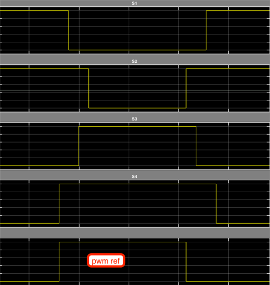
Scheme A
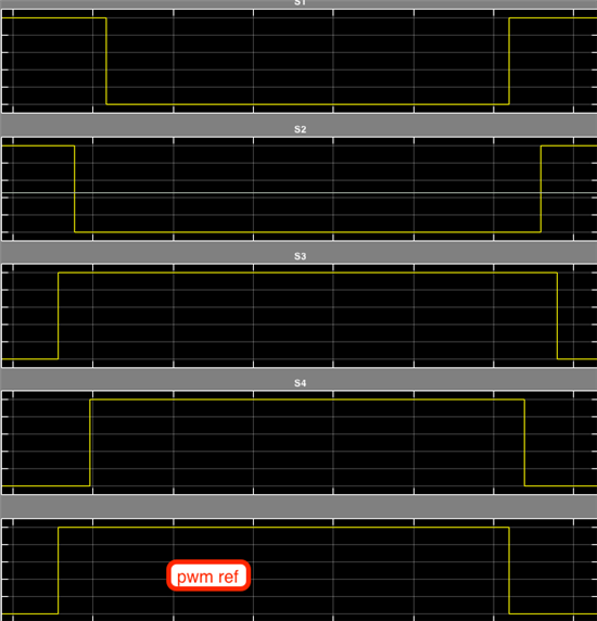
Scheme B
I'm trying to figure out how to implement the 2 different commutation schemes above with the ePWM module in F28069.
The order in which the switches are turned on are very important, and I'm trying to figure out the best way to implement.
Switch orders are S4, S1, S3, S2 and then S2, S3, S1, S4 for Scheme A.
Switch orders are S3, S2, S4, S1 and then S1, S4, S2, S3 for Scheme B.
HRPWM would be nice to use (but not necessary), but then I would not be able to use deadband submodule. If I decide to go with HRPWM, I would use PWMA of 4x PWMs, that way each has HR.
If I don't use HRPWM, then I could use the DB submodule. However, the DBs are different according to which scheme I am in (A or B). They can be viewed in 2 different ways:
In Scheme A,
- S1 and S3 are AHC (active high complementary)
- S2 and S4 are ALC (active low complementary)
In Scheme B,
- S1 and S3 are ALC (active low complementary)
- S2 and S4 are AHC (active high complementary)
Alternatively, one could say that in either scheme (except PWMs are swapped in opposing schemes),
- S1 and S2 are AL (active low)
- S3 and S4 are AH (active high)
My thinking is once I detect which scheme I should be in, I could adjust my DBRED/FED and DBCTL[POLSEL] for each one. My concern is that if I am dynamically changing the DBRED and DBFED registers, when do they go into effect? Is this immediate on the next TBCLK edge? Or does it happen when CMPA/CMPB are loaded?
If the effect is immediate, then there is a potential situation that if I load values into DBRED/DBFED/DBCTL[POLSEL] at the wrong time, it could cause problems.
Is the best solution to just adjust CMP values for deadband instead of using DB submodule? An added bonus is that this would allow me to use HRPWM if I'm not using DB submodule. Just looking for ideas on the most effective and efficient way to implement this using ePWM module.


